Logic Function Optimization
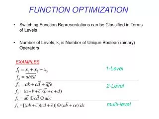
Logic Function Optimization. Combinational Logic Circuit. Regular SOP and POS designs Do not care expressions Digital logic circuit applications Karnaugh Maps Minimization of logic functions. Combinational Logic Circuit. The function D=A’B’C’+A’BC’+ABC’+ABC

Logic Function Optimization
E N D
Presentation Transcript
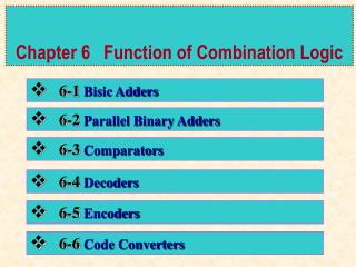
Combinational Logic Circuit • Regular SOP and POS designs • Do not care expressions • Digital logic circuit applications • Karnaugh Maps • Minimization of logic functions
Combinational Logic Circuit The function D=A’B’C’+A’BC’+ABC’+ABC can be implemented in the sum of products (SOP) form as follows: Minterm: Product that contains all input variables or their complements for which function value is 1
Combinational Logic Circuit The function D=(A+B+C’)(A+B’+C’)(A’+B+C)(A’+B+C’) can be implemented in the product of sums (POS) form as follows: Notice that SOP and POS forms can be implemented in such regular designs for any function.
Combinational Logic Circuit Find canonical sum of products (SOP) form for the following function F=AB’+A’C+ABC’ can be implemented in the : We have: F=AB’C+AB’C’+A’BC+A’B’C+ABC’
Combinational Logic Circuit Theorem: Each function can be represented in the unique form of SOP or POS. Let us obtain POS from for the following function: D=A’B’C’+A’BC’+ABC’+ABC Using DeMorgan’s law D’=(A’B’C’+A’BC’+ABC’+ABC)’= =(A+B+C)’(A+B’+C)’(A’+B’+C)’(A’+B’+C’)’
Do not Care - Logic Circuit Do not care condition is when the output function value is not important for a specific input combination
Do not Care - Logic Circuit Do not care can be used to simplify the circuit implementation
How to Design a Digital Logic Circuit? How to translate a desired circuit functionality into a truth table? To design a digital logic circuit to control LED display we must first come up with a truth table.
Digital Logic Circuit Output Then each output ABCDEFG must be implemented as a separate logic function of 4 input bits xywz that represent BCD code of integer value
Digital Logic Circuit Output For instance to control the segment A the logic function is FA=a’b’c’d’+a’b’c+a’bd+ab’c’ or for segment B FB=a’b’+a’bc’d’+a’bcd+ab’c’
Binary-Octal Decoder Circuit Design example
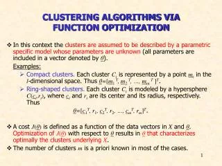
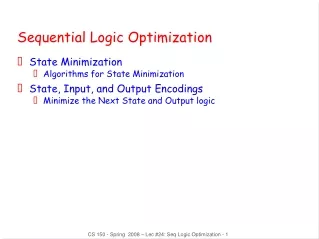
Karnaugh Maps in Logic Circuit Karnaugh maps can be used to simplify the logic function and its design
Karnaugh Maps in Logic Circuit Karnaugh map uses hypercube with the same function value in the whole cube to reduce the number of terms in the logic function
Karnaugh Maps in Logic Circuit The whole cube in the Karnaugh map is represented by a single product term. For instance cubes in the example figure are. (a) ab’ (b) ab (c) a’b’
Karnaugh Maps in Logic Circuit Use Karnaugh maps to obtain minimum SOP for these functions: Z=W’X’Y’+W’XY’+WX’Y+WXY D=A’B’C’+AB’+A’B’C E=ABD’+A’BCD’+ABC’D
H 1 0 0 x L D 1 0 1 x D F L H Do not Care - Logic Circuit F=L’+DH’
Digital Logic Circuit Output Using Karnaugh map we can minimize FA=a’b’c’d’+a’b’c+a’bd+ab’c’=b’c’d’+ab’c’+a’bd+a’b’c B A D C
Output A of 7 Segments Decoder Segment A logic function is FA=a’b’c’d’+a’b’c+a’bd+ab’c’ With do not cares FA=a+a’b’c’+bd+cb’ B A D C
Digital Logic Circuit Output Using Karnaugh map we can minimize FB=a’b’+a’bc’d’+a’bcd+ab’c’= =b’c’+a’c’d’+a’cd+ a’b’ B A D C
Digital Logic Circuit Output Using Karnaugh map we can minimize FB=a’b’+a’bc’d’+a’bcd+ab’c’= =a’b’+ b’c’+a’c’d’+a’cd With do not cares FB=c’d’+cd+b’ B A D C