All-IP RAN interworking
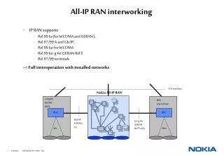
CRMS. RNGW. RNAS. CSGW. CRMS. SMLC. SMLC. LMU. IP BTS. OMS. All-IP RAN interworking. IP RAN supports Rel 99 Iu (for WCDMA and GERAN ), Rel 97/99 A and Gb/IP, Rel 99 Iur for WCDMA Rel 99 Iur-g for GERAN Rel'5 Rel 97/99 terminals --> Full interoperation with installed networks.

All-IP RAN interworking
E N D
Presentation Transcript
CRMS RNGW RNAS CSGW CRMS SMLC SMLC LMU IP BTS OMS All-IP RAN interworking • IP RAN supports • Rel 99 Iu (for WCDMA and GERAN ), • Rel 97/99 A and Gb/IP, • Rel 99 Iur for WCDMA • Rel 99 Iur-g for GERAN Rel'5 • Rel 97/99 terminals --> Full interoperation with installed networks CN interface Nokia All-IP RAN UTRAN Rel'99, Rel4 BSS any release RNC BSC Rel 99 UTRAN Iur Iur-g for GERAN Rel'5 only Iub Abis
Traffic growth scenario Optimized architecture/ products for these worlds ? Bits/s BH / user MBytes / user / day ~60/20/20 % traffic reference: best effort packet/ CS-voice/ RT packet data) 'application' bits over Air interface
Radio NW Access Server Common Radio Resource Server O&M Server Upgrades to Nokia UltraSite and MetroSite EDGE / WCDMA Base Stations A and Iu-cs Nokia FlexiServer Nokia CS Gateway Gb IP / ATM / MPLS transport Iu-ps Nokia RN Gateway Multimode All-IP Base Station GSM/EDGE/WCDMA WLAN Nokia distributed All-IP RAN architecture • Multiradio architecture, with multimode All-IP BTS • User plane and Control plane separated to allow optimised handling • Dynamic association between BTS and Radio Access Servers • Radio interface performance critical functions located in the BTS, close to radio • Transport optimised by relocating functionalities
Core Network Gateways Platform: IPA2800 IuPS Cplane IuPS Uplane Platform: IP740 Platform: FlexiServer Iu-CS A BSSAP/RANAP relay RNAS RNGW: RAN Gateway RNGW Ctrl CSGW Ctrl CSGW: Circuit Switched Gateway RNAS: RAN Access Server BSSAP'/ RANAP' Iu-PS Ctrl A/IP, Iu-CS/IP Iu-PS BSGW UCF BSGW • RNGW • RAN Gateway is the user plane gateway for IP traffic. • Micromobility anchor for Iu-PS Uplane • Firewall t.b.d. • RNAS • Radio Network Access Server is the control plane gateway for RAN-external signaling. • Micromobility anchor for Cplane (terminates the signaling bearer connections, and relays L3 messages) • Paging Server • O&M of CN interface (reset, overload) • RNGW and CSGW control • CSGW • Circuit Switched Gateway is the user plane gateway for non IP traffic • ATM to IP interworking (Iu-CS and Iur, both Cplane and Uplane • PCM to IP Interworking (A, Uplane and Cplane) • Transcoding • Micromobility anchor for A and Iu-CS Uplane
RAN Common Servers Common Resource Management Server Serving Mobile Location Centre O&M Server Platform: FlexiServer • CRMS • Common Radio Resource Management Serverperforms RAN Wide Radio Resource Management (inter cell/layers/system) • Load sharing • Policy Management • Autotuning for load sharing between layer • OMS • O&M Servers performs RAN O&M functions • Connection to OSS • Logical O&M • System Info Broadcast • Configuration Manag. • Performance Manag. • Fault Manag. • Autotuning features • SMLC • Serving Mobile Location Center performs UE PositioningCalculations • Support of multiple positioning methods • Support of positioning request through 2G and 3G core • LMU control and O&M
UE Control Function • Termination of the CN signalling • Radio signalling (RR, RRC) • RAB Admission control • Handover control • Initialisation of dedicated resources in the network • Base Station Gateway • Termination of CN interface user plane • PDCP, RLC, MAC-d • MDC (Soft Handoff) • Ciphering CN Cplane CN Uplane External Iur: one UE may use UCF/BSGW in Serving BTS, and CRS/CGW(L1) in drift BTS ULTRA upgrade RR O&M UCF BSGW OMS • Cell Gateway • GERAN PCU • WCDMA PS for shared and HS data channel • Retransmission • Cell Resource Server • GRR protocol • Radio Admission control • Channel allocation and resource reservation • Load Control (Iub / Abis) BTS L1 LMU SMLC • BS O&M • Termination of logical O&M interface • Implementation specific O&M Location Measurement Unit Could be external to the IP BTS BTS L1: Same functionality of Rel'99 BTS and Node B All-IP BTS CRS CGW
High level BTS integration • Example configuration • 3 sectored 2+2+2 solution • 384 code channels • multi-mode upgradeable Expansion slots
RNC RNC RNC CSGW CSGW RNC RNC RNC RNC RNC RNC CSGW RNC RNC RNC RNC RNC RNC RNC RNGW RNGW Comparision, RNC functionality in IP RAN • Assumptions based on Peritus y. 2008 • PS traffic: 12174 Mbit/s • CS tarffic: 4870 Mbit/s • subscribers: 13,6 M • -> 168 rack s RNCs ( or 676 racks BSS11 BSC ) • -> 5 racks RNAS • -> 30 racks CSGW • -> 15 racks RNGW • = 50 racks with IP RAN RNAS One rack = 10 racks
All-IP Indoor Supreme BTS • High Capacity All-IP BTS • Supports 1-9 sectored solutions • up to 36 WCDMA carriers per cabinet • up to 1152 code channels per cabinet • multi-mode capable with All-IP RAN rel. 2 • ideal for multi-operator RAN • full support for Nokia Smart Radio Concept • ideal for indoor installations • Co-siting with existing BTS sites • Dimensions H x W x D 1800 x 600 x 600 mm • Operating temperature range -40 … +50 C • Mains Supply -48 VDC or 230 VAC
All-IP Outdoor Compact BTS • High Capacity All-IP BTS • Supports 1-9 sectored solutions • up to 36 WCDMA carriers per cabinet • up to 1152 code channels per cabinet • multi-mode capable with All-IP RAN rel. 2 • ideal for multi-operator RAN • full support for Nokia Smart Radio Concept • ideal for outdoor installations • Co-siting with existing BTS sites • minimized site requirements due to small size • unobtrusive in roof top installations due to low cabinet height • Dimensions H x W x D 1500 x 770 x 770 mm • Operating temperature range -40 … +50 C • Mains Supply -48 VDC or 230 VAC
All-IP Upgrade to Ultrasite WCDMA BTS • Base station (BTS) software upgrade for new functionality: • Iub over IP in R4 network • All-IP RAN BTS in R5 • Transport upgrade: • new IP router unit (IRIS), • reuse of RAN1/RAN2 IFUs (IP over ATM), or • introduction of new IP IFUs (no ATM)
All-IP RAN Server Configurations - Examples OMS+RNAS+CRMS ( ca. 1.5M subs ) OMS+RNAS+CRMS+SMLC ( ca. 3 Msubs ) OMS+SMLC (ca. 1.5M subs) OMS+CRMS ( ca. 1M subs ) • Flexible configuration of nodes to different server applications; max. 44 nodes per rack • Connectivity to 1000 IP-BTS, max. 6000 IP-RAN cells; Capacities/node estimates with current call-mix assumptions for 2008: RNAS 150k subs, CRMS: 250k subs, SMLC: 375k subs HDD OMS RNAS SMLC CRMS
All-IP RAN Servers - Server Blades HW • 9/11/12 nodes per subrack, two CPUs per node => 88 CPUs per rack • duplicated IP director per rack (one IP address, or very few addresses, visible to external network) • Pair of disks per rack (exact location in the rack FFS) Up to 12 CPU slots Chassis Fan tray,displaypanel Cabinet 2 x LAN switches & Fiber Channel hubs,System mgt functions IP Director CPU Disk Drive
RNGW • IP740 platform • 19" racking • User plane throughput 44 Mbps per RNGW (200 byte packets), 150k RABs (max. 2.5k Handovers/s) • max. 18 RNGWs per rack => 792 Mbps and 2.7M RABs per rack
1 2 3 4 5 6 7 8 9 10 11 12 13 14 15 16 17 18 19 TSS3 MXU 0/ 0 SPMU / 0 (NEMU) WDU / 0 WDU / 0 CACU / 0 OMU / 0 NIS1/ 0 SFU /0 NEMU CM / 0 EHU x x x x NIS0/ 0 / MX622-B CCP10 (NEMU) CCP10 CCP10 MCPC2 CCP10 ESA12 (OMU) EHAT TBUF SF10 HDS HDS PD20 x x x 1 2 3 4 5 6 7 8 9 10 11 12 13 14 15 16 17 18 19 TBUF MXU 0/ 1 SPMU / 1 NIS1/ 0 CACU / 1 WDU / 1 WDU / 1 OMU / 1 CM / 1 SFU /1 ISU FDU x x x ) NIS0/ 0 / CCP10 MX622-B CCP10 (NEMU) CCP10 OMU CCP10 CCP10 (OMU) SF10 PD20 TSS3 MDS HDS HDS x x ( 1 2 3 4 5 6 7 8 9 10 11 12 13 14 15 16 17 18 19 TBUF TBUF A2SU A2SU IPNIU TCU A2SU TCU TCU TCU IWU IWU TCU IWU TCU TCU MXU MXU MXU MXU TCU TCU TCU TCU TCU TCU TCU TCU TCU TCU TCU TCU TCU ISU ISU x x x IPS1/IPGE MX622-B MX622-B MX622-B MX622-B IW16P1 IW16P1 IW16P1 CCP10 CCP10 CDSP CDSP CDSP CDSP CDSP CDSP CDSP CDSP CDSP CDSP CDSP CDSP CDSP CDSP CDSP CDSP CDSP CDSP CDSP CDSP TBUF TBUF PD20 PD20 AL2S AL2S AL2S x 1 2 3 4 5 6 7 8 9 10 11 12 13 14 15 16 17 18 19 TBUF A2SU A2SU A2SU IPNIU TCU TCU MXU TCU TCU MXU TCU TCU TCU TCU TCU ISU x x IPS1/IPGE MX622-B MX622-B AL2SU AL2SU CCP10 AL2SU CDSP CDSP CDSP CDSP CDSP CDSP CDSP CDSP CDSP TBUF PD20 x CSGW • IPA2800 platform • 1800 * 600 * 600 mm (H*W*D) rack • 10 000 Iu-CS channels per rack 1 cabinet 10000 channels
RNC SDH/DWDM OSR LAN/WAN connectivity(IP/MPLS) GSR Core Site Solution ( incl. All-IP RAN Servers ) Core Site (IP/MPLS) SGSN HSS CPS MSC Server GGSN MGW RNGW Inter-connects CSGW All-IP RAN Servers IP ATM
Radio Performance gains in All-IP RAN • Introduction / Background • User Plane packet channel Gains • Control Plane packet channel Gains for Packet Services • Combined results • Other Potential Gains • Summary
Radio performance in All-IP RAN -Setting up a session for a transport protocol (e.g. TCP) is quicker in IP RAN due to faster transport and smaller RLC RTT - User experiences smaller delay in setup phase. Router All-IP BTS Mobile RLC Transport Protocol RLC - Transport is based on fast IP routing in IP RAN. - 'Information highway' ends in RNC in UTRAN, but lasts till IP BTS in IP RAN. - Routing of a packet from CN to IP BTS takes only few ms. No Iub in IP RAN --> - Smaller RLC RTT - quicker RLC retransmissions - User experiences better bit rate for bursty traffic
Minimum allocation time of channels Channel Allocation Time Gain User Plane Gain Release Timer Gain Control Plane Gain User Plane Gain: Shorter RLC RTT gives faster transmission of user data. Release Timer Gain: Faster allocation time gives that the release timer can be reduced. Channel Allocation Time Gain: Shorter allocation time of DCH/DSCH gives higher availability of codes and increased capacity. Control Plane Gain: No Iub interface setup time, gives faster setup of the DSCH and associated DCH All-IP RAN Gains for Packet ServicesDetails on the transmission of a data burst Iub Setup Scheduling, RF meas. and pwr calc. Transmission on DSCH Release Timer Iub Release UTRAN Scheduling, RF meas. and pwr calc. Transmission on DSCH Rel. Timer IP RAN time Start: Packet scheduler decides to use DSCH transmission
User Plane Gains for Packet Services (I) • Assumptions: • - TCP/IP traffic, e.g. web browsing, single object per page: TCP algorithms (slow start with 1 Maximum Segment Size initial window, MSS = 1460 B, delayed TCP acknowledgement) • - TCP session setup: 3-way handshake (3 messages, last setup message contains HTTP request) • - RLC RTT 140 ms for UTRAN and 70 ms for IP RAN • - Block Error Rate over radio 10% • - Constant user bitrate over the radio interface • - CN RTT 65 ms (web server very close to RAN). No server processing time. • Experienced Bit Rate: user bits / total TX time, without DSCH/DCH allocation delay • Gain (%): how much better experienced bit rate IP RAN gives compared to UTRAN with Iub interface • Result evaluated for WCDMA case, similar results for GERAN
User Plane Gains for Packet Services (II) • Gain depends, for example, on the allocated user bit rate, RLC BLER and the page size. Page sizes • The smaller the page the more gain -> the gain in the beginning of downloading • The bigger the user bit rate the more gain -> the big bitpipe used more efficiently in All-IP RAN
Control Plane Gains for Packet Services (I) • The Control Plane (ex: allocation and release of radio channel, channel switch, etc) is more efficient in All-IP RAN than in UTRAN, mainly thanks to that there is no Iub interface. • The gain from the more efficient Control Plane is especially large for packet services, due to the frequent change of state. • Evaluation: Find the improvement in download time • for files of different sizes • for different user bit rates on the air interface • Assumption: Iub setup time=350msec, other parameters like in previous example.
Control Plane Gains for Packet Services (II) • Note that the above gains are found within Control Plane alone • In general, the gain is between 10 and 30%. • Gain is highest for small files and high bit rates • For most common file sizes and user bit rates, the gain is about 20 - 25%
Combined User Plane and Control Plane Gains • The combined User and Control plane results for Gain expressed in in terms of delay gains: -> DELAY REDUCTION UP TO 40 %
Other gains expected from optimization of RRM algorithm • Note that HSDPA (High Speed Packet Access) is • going in the same direction as All-IP RAN: • HSDPA scheduling moved to Node B • However, solution more complex as scheduling • for other channels are kept in the RNC. • All-IP RAN overcomes this problem! • Reasons: • Measurements from UE and from IP BTS are available in the same node • RRM algorithms are preferably located as close as possible to the radio • Proprietary BTS measurement are available for new optimized RRM algorithms and capacity enhancing features (no need of 3GPP Iub standardization) • Example: • Imagine that an enhanced algorithm need a new measurement in the BTS. • In IP RAN, we implement it without waiting for 3GPP. • In UTRAN, this measurement needs to be standardised on the Iub interface, meaning that we need to merge our proposal with the opinions from other companies.
Conclusions • Users experience better service in All-IP RAN for packet data, with delay for the transmission of a packet reduced up to 40% • Reduced code allocation time. • Potential optimization of RRM algorithm without the burden of using the predefined Iub measurement
Input parameters • IP Router Buffer Sizes: • Leaf BTS, 30 kbytes (leaf means last BTS in the tree topology) • Other BTSs, 100 kbytes
DS Rt_Core 27.66 Mbps 30.04 Mbps DS Rt_A1 1.92 Mbps 2.05 Mbps DS DS 2.21 Mbps Rt_A Rt_A2 DS DS 2.05 Mbps Rt_D1 DS DS Rt_B1 21.67 Mbps Rt_E4 23.93 Mbps 2.05 Mbps 2.05 Mbps DS Rt_B 2.05 Mbps 2.05 Mbps DS 2.05 Mbps Rt_B2 DS 2.05 Mbps Rt_E1 2.23 Mbps 4.70 Mbps 9.00 Mbps 8.61 Mbps 2.05 Mbps DS 2.07 Mbps Rt_E2 DS DS DS 2.05 Mbps Rt_B3 Rt_F3 Rt_F DS DS 2.05 Mbps Rt_C3 Rt_C 2.04 Mbps 2.22 Mbps DS 2.19 Mbps Rt_B4 2.05 Mbps DS 2.05 Mbps DS Rt_B5 Rt_F2 DS DS DS Rt_G1 Rt_C2 DS Rt_C1 Rt_F1 • IP RAN • 40% SHO OH for RT traffic only • IPv6 • transport UDP/IP compressed • MDC in first starpoint DS Rt_D2 Rt_D DS Rt_E3 DS Rt_E DS Rt_G
RAN 1 • 40% SHO OH for RT and NRT traffic • No Stat Mux gain • No centralised AAL2 42,6Mbps 46,86Mbps 4,26Mbps 4,26Mbps 4,26Mbps 4,26Mbps 38,34Mbps 4,26Mbps 34,08Mbps 4,26Mbps 4,26Mbps 4,26Mbps 4,26Mbps 4,26Mbps 12,78Mbps 12,78Mbps 8,52Mbps 4,26Mbps 4,26Mbps 4,26Mbps 4,26Mbps 4,26Mbps 4,26Mbps 4,26Mbps 4,26Mbps 4,26Mbps 4,26Mbps
RAN 2 • 40% SHO OH for RT traffic only • Centralised AAL2 34.54Mbps 31.4Mbps 3,14Mbps 3,14Mbps 3,14Mbps 3,14Mbps 28.26Mbps 3, 14Mbps 25,12Mbps 3,14Mbps 3,14Mbps 3,14Mbps 3,14Mbps 3,14Mbps 9,42Mbps 9,42Mbps 6,28Mbps 3,14Mbps 3,14Mbps 3,14Mbps 3,14Mbps 3,14Mbps 3,14Mbps 3,14Mbps 3,14Mbps 3,14Mbps 3,14Mbps
Comparison • RAN2 with centralised AAL2 compared with RAN 1 saves 15% - 30% in capacity • 15% is here refered to modest and 40% aggressive case of saving with Centralised AAL2 of RAN2 • Additional saving of RAN2 compared with RAN1 is the NRT traffic not having SHO OH Comparison against RAN1 Comparison against RAN2 ( 15 % )
Common Radio Resource Management (CRRM) Seamless integration of radio technologies to ensure optimum end user performance and resource usage GSM/EDGE Macro WCDMA GSM GSM Micro WCDMA WCDMA GSM/EDGE multi-mode terminal WLAN WCDMA Pico TDD • Better capacity& quality level • Offer higher user bit rates and lower blocking • Enable load sharing and congestion control • Distribute interference • Enable multivendor RRM interoperability • Easier operability • Simple interworking in multi-vendor / multi-system environment
CRRM Cell Loads & QoS xRAN Set HO Parameters CRRM Handover Candidates xRAN Prioritized List CRRM Interfaces & Function • Nokia CRRM can connect to many different radio interface technologies • New standardisation is needed for an open multivendor CRRM interface CRRM server RNC IP-RAN WCDMA Other.. TDD, WLAN,.. GSM/EDGE BSC • CRRM acts as an advisor to each system when making decisions • CRRM server is also the platform for other functions eg. • Setting idle mode parameters • Fast auto tuning
CRRM Simulation Results - Summary QoS class Capacity gain with 2 layers Capacity gain with 4 layers Reason for the CRRM gain • CRRM is most important • for interactive connections • for high bit rate (>32 kbps) conversational and streaming connections • when large number of layers and systems are integrated • Note: these gains are fairly ideal gains assuming no delays in signaling etc. With proper CRRM algorithms most of these gains can be obtained in practice Conversation Streaming No gain 32 kbps 3% 144 kbps 10% 384 kbps 30% Timers are needed to prevent ping-pong (and also useful handovers) without CRRM Interactive 40%-100% depending on the required delay 70%-140% depending on the required delay No load reason inter-system cell reselections assumed without CRRM Background Less gain than with interactive if no delay is guaranteed