Download
1 / 33
330 likes | 362 Views
Explore the latest advancements in PCB design for DUNE projects, focusing on high-voltage safety, improved hardware, and quality control methods. Enhancements include increased wire trace spacing and custom connectors. Efforts to enhance assembly processes and inspection tools are also highlighted.

E N D
Printed Circuit Board Design Updates Andrew Laundrie and Xu Zhai UW Physical Sciences Laboratory March 27, 2019
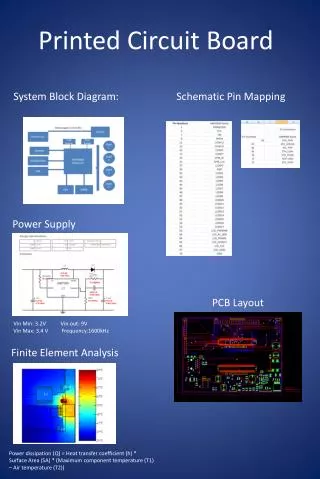
Design Updates ̶ Overview • Foot Boards and Side Boards • Dimensions stretched to fit larger frame tubes • Multi-layer boards are required in some locations • Head Boards • Increased spacing between wire traces • Improved interface for electrical testing • Hardware Improvements • Custom Mill-Max sockets and pins • Stronger threaded inserts in boards DUNE PCB Design Updates
X-Layer Foot Boards Old New DUNE PCB Design Updates
V-Layer Side Boards DUNE PCB Design Updates
U-Layer Side Boards DUNE PCB Design Updates
Head Board Structure DUNE PCB Design Updates
Slots Between CR Boards DUNE PCB Design Updates
X-layer Head Board: ProtoDUNE Solder Pads (48) X Plane Sockets and Test Pads (48) VSS pass-throughs V U V and U signals pass through connected socket pairs DUNE PCB Design Updates
X-layer Head Board: ProtoDUNE • Spacing of 0.5 mm between channels limits the safe voltage that can be applied between adjacent wires (~100 V) • Increased spacing is desired to support voltage differences as high as 400 V DUNE PCB Design Updates
X-layer Head Board: DUNE DUNE PCB Design Updates
X-layer Head Board: DUNE • Spacing between U and V wire channels has increased to 2.5 mm • Board edge was moved 4.0 mm to accommodate increased channel spacing • Fiducials were added to all boards to support inspection by automatic vision systems Fiducial reference point V U DUNE PCB Design Updates
X-layer Head Board: DUNE • Landing pads were added to the bottom side of X head boards (blue traces) • Pads allow the attachment of test headers in place of CR boards • Headers use spring-loaded contact pins DUNE PCB Design Updates
Test Header Concept • Four connectors provide access to all channels on the X, U, and V head boards DUNE PCB Design Updates
CR Board (ProtoDUNE) DUNE PCB Design Updates
New CR Board Minor changes only DUNE PCB Design Updates
V-layer Head Boards (new / old) DUNE PCB Design Updates
U Layer Head Boards (new / old) DUNE PCB Design Updates
G Layer Head Board: ProtoDUNE Solder Pads (48) Landing pads for G bias (12 + 6) DUNE PCB Design Updates
G Bias Board: ProtoDUNE DUNE PCB Design Updates
G Layer Head Board: DUNE Solder Pads (48) Landing pads for G bias (48 + 6) DUNE PCB Design Updates
G Bias Board: DUNE DUNE PCB Design Updates
ProtoDUNE Sockets and Pins Standard catalog items had some performance issues DUNE PCB Design Updates
DUNE Sockets DUNE PCB Design Updates
DUNE Pins DUNE PCB Design Updates
CE Assembly Installation • Captive screws in ProtoDUNE were meant to pull connectors together in a controlled fashion, but they posed arisk of being dropped into the cryostat during CE installation or removal DUNE PCB Design Updates
CE Assembly Installation • Captive screws were eliminated by changing the angle brackets on CR boards • Threaded tools are inserted and rotated to pull connectors together, then removed DUNE PCB Design Updates
CE Assembly Installation DUNE PCB Design Updates
Hardware Improvements • Expanding threaded inserts have been replaced by broaching fasteners to prevent breaking and reduce metal debris DUNE PCB Design Updates
Process Improvements • Improved tools and methods are being evaluated for PCBs • Instrumented tips on soldering irons for process control • Vapor-phase reflow soldering for CR and G Bias boards • Improved board-washing equipment • Automated test systems for CR boards and G-Bias boards DUNE PCB Design Updates
Quality Assurance and Control • All ProtoDUNE boards were inspected when received • Complex mechanical features were frequently out of spec • Continued inspection of most boards is probably needed • Manual board inspection was time-consuming • Vision systems are being evaluated for board inspection DUNE PCB Design Updates
Backup Slides DUNE PCB Design Updates
Mill-Max Pins and Sockets Pins are fragile and not repairable once bent. Their exposure is minimized during APA assembly. . U V CR X
In ProtoDUNE the separation between exposed metal through-hole pads is about 0.5 mm.