Download
1 / 12
120 likes | 678 Views
Synthesis gas production using secondary Reforming in ammonia production. Group: Ahmed Nasr Abu El Magd ID : 310018 Serein Abdel Hameed Mohamed ID : 309290 Alsyed Reda Alsyed ID : 309288. Introduction.

E N D
Synthesis gas production using secondary Reforming in ammonia production • Group: • Ahmed Nasr Abu El Magd ID : 310018 • Serein Abdel Hameed Mohamed ID : 309290 • Alsyed Reda Alsyed ID : 309288
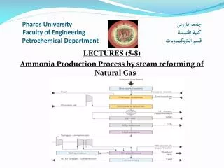
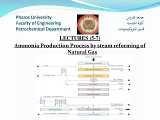
Introduction In a traditional ammonia plant, the secondary reformer is rather used downstream of the primary reformer in order to reform the unreacted methane to produce Hydrogen and Nitrogen. The reactor consists of two sections, the combustion section is the empty space above the catalyst section is preferred to combust process gases with oxygen of the air to produce the Nitrogen while, the catalytic section is a fixed-bed reactor, in which the hydrocarbons are finally converted through heterogeneous catalytic reactions to produce the Hydrogen. It is provided with Ni/MgOAl2O3 as a catalyst, Finally, the Reformat Gases leaves the secondary reformer, as shown in the Figure 1.
1) Burner; 2) Combustion section; 3) Alumina bricks plate; 4) Alumina balls (dia. = 40 mm); 5) Catalyst section; 6) Alumina balls (dia. = 40 mm, 75 mm and 120 mm); 7) Cone.
Combustion Section The hydrocarbon (CH4) and oxygen in the air are mixed and combusted in the combustion section of secondary reformer reactor. Often the principle “mixed is burnt” is valid, since the exothermic combustion reactions are very fast. The homogenous reactions are take place in the com- bustion section. The combustion reactions are numerous complex radical reactions, but for modeling purposes, it is often enough to describe the reactions by an overall one molecular reaction. In the case of natural gas, the combustion methane reaction can be written as follows: CH4 + 3/2 O2 → CO + 2H2O ΔHr= -519.760 kJ mol (1) All oxygen is consumed in the combustion section, and the unconverted CH4 will continue down to the catalyst section. In the case of a secondary reformer also, H2 will be burnt to steam in the combustion section according to reaction. H2 + 1/2 O2 → H2O ΔHr= -242 kJ/mol(2)
Catalyst Chemical Reaction The product gas from the combustion section is directed to the catalytic section of the secondary reformer. The catalyst bed involves three reversible reactions, which were thoroughly studied by Xu and Froment (1989). The first reaction is known as a Steam Methane Reforming reaction while the second and third reactions are called as Water Gas Shift reaction and Carbon Dioxide Reforming reaction respectively. Anyway, the following equations can be written as follows: The C-H bond of the stable methane molecule (CH4) has a high binding energy (439 kJ/mol) therefore, the dissociation reaction of steam methane reforming needs a high process temperature to shift the equilibrium com- positions to the right side so the steam methane reforming reaction is endothermic
Catalyst Section Temperature Calculation for Gases and Catalyst Surface The temperature is considered a very important factor due to the nature of chemical reactions on the catalyst section. These reactions are extended from endothermic to exothermic. The relation between the temperature of gases and surface of catalyst as a function for axial coordinate of catalyst bed has been described in Equations 24 and 25. depict that the catalyst (RKS - 2 - 7H’) was more active than the other catalyst types (RKS - 2, ICI 54 - 2, RKS - 2 - 7H” and RKS-2 - 7H”’) respectively relative to the reactions conditions because the temperatures of gases and catalyst surface are lower than the temperatures in the other types of catalysts due to end- thermic reactions that means the rate of reactions on the catalyst surface (RKS-2-7H’) are faster than other types of catalysts.
Pressure Drop • The pressure drop gives a good indication about catalyst performance inside the reaction shell because with a long time of operation; the catalyst may be thermal cracking due to high operation temperature so, the value of pressure drop will increase. • When the heat load per unit area is too high, smaller particles will be necessary in order to increase the surface area of the catalyst but, smaller particles will lead to in- crease the pressure drop. Therefore, selecting special catalyst shapes such as rings or rings with several holes have been developed for these applications . • The behavior of pressure drop has been described in Equation (26) which depicts a decrease along the axial distance from the top of the catalyst bed. depicts the value of outlet pressure as a function of reactor length for five different types of catalysts.
The Shape of Pellet • The shape of the catalyst pellet is considered a very important parameter. Rings with several holes are suitable shape amongst secondary reforming catalysts because it pro- vides a higher surface area per unit volume i.e. the specific surface area of the pellets (S) as summarized in Table 3.
The Total Surface Area of Catalyst Pellets in Catalyst Section • Using the smallest of the pellet in the catalyst zone is necessary for available high total surface area of catalyst pellets in catalyst section as shown in Table 3.
Volume of Pellet • The diffusion into the pellet is relatively slow, so that this condition mean reaction occurs before the reactant has diffused far into the pellet. Also, the effectiveness factor that means only the surface near from the outer surrounding of the pellet is effective, therefore, the diffusion and effectiveness factor gave a good indication about the shape of the catalyst that is used in the catalyst zone as a ring without central portion because the chemical reaction takes place at the outer surface [1], then the volume of RKS-2-7H’ pellet (Cylinder with 7 holes) has least volume of pellet because it has least dimensional and thin of walls than other pellets as shown in Table 3.
Table 3. Types of catalysts characteristics used in secondary reformer.
REFERENCE • A. A. AL-Dhfeery and A. A. Jassem, “Modeling and Simulation of an Industrial Secondary Reformer Reactor in the Fertilizer Plants,” International Journal of Indus-trial Chemistry • J. A. C. Ruiz, F. B. Passos, J. M. C. Bueno, E. F. Souza-Aguiar, L. V. Mattos and F. B. Noronha, “Syngas Production by Autothermal Reforming of Methane on Supported Platinum Catalysts,” Applied Catalysis A: General, Vol. 334, No. 1-2, 2008, pp. 259-267. doi:10.1016/j.apcata.2007.10.011 • K. Khorsand and K. Deghan, “Modeling and Simulation of Reformer Autothermal Reactor in Ammonia Unit,” Journal of Petroleum and Coal, Vol. 49, No. 2, 2007, pp.