IBS
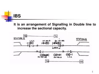
IBS. It is an arrangement of Signalling in Double line to increase the sectional capacity. IBS. REQUIREMENT:. One Block Section is divided into two portions (a) Rear Section (b) Advance Section Axle Counters with Reset for each rear section.

IBS
E N D
Presentation Transcript
IBS It is an arrangement of Signalling in Double line to increase the sectional capacity.
IBS REQUIREMENT: One Block Section is divided into two portions (a) Rear Section (b) Advance Section Axle Counters with Reset for each rear section. Miniature panels with push Button and indication at each Block station. IB Signal and Distant Signal for each direction. Conventional Double line Block Instruments at each Block Station. Magneto Telephone communication with station in rear from each IB Signal.
REAR SECTION: (a) Section between LSS and IB Signal (including 400 meters Block overlap) (b) Entry into “Rear Section” is controlled by LSS (c) LSS a controlled by clearance of the (rear section) Axle Counter (d) LSS in taken off by station in rear. (Axle Counter with reset for rear section is kept at rear station only)
ADVANCE SECTION: • (a) Section between IB Signal and FSS of station in advance Including Block overlap. • (b) Entry into “Advance Section” is controlled by IB Signal • (c) IB Signal is controlled by line clear of Block instrument obtained from station in advance. • (d) IB Signal is taken off by Station Master in rear.
EVALUATER • AXLE COUNTERS:One Axle Counter with reset systems for each rear section is kept at sending station. Axle Counter Evaluator is provided in rear station.
MAGNETO TELEPHONE • MAGNETO TELEPHONE: Provided at IB Signal for Communication with station master in rear. • TELEPHONE OUT OF ORDER: In case IB Signal at “ON” and if the Telephone is not working the driver has to wait at IB Signal for 5 minutes by Day/Night and pass IBS at ‘ON’ if not cleared, with speed not more than 15 KMPH when view ahead is clear and not more than 8 KMPH when view ahead is not clear .
INDICATIONS ON IBS. PANEL • K1 :Indication appears at sending station when a train passes IBS at danger with buzzer sound. • When acknowledgement button is pressed buzzer stops,K1 appears till IBS which was failed has to be rectified. • c) K2 : Indication appears with buzzer sound at sending station when a train passed LSS at off. • Indication & buzzer sound disappears when LSS levers/switch replaced to normal. • d) K3 : Indication appears with buzzer sound at sending station when a train passes IBS at off. Indication & buzzer sound disappears when IBS levers/switch replaced to normal
.d) K4 : Indication appears with buzzer sound at sending station when power failed or signal bulb fused at IB Signal or IB distant signal • When acknowledgement button is pressed buzzer stops,K4 appears till fault is rectified
BUTTON: • BUTTON: PB1: Pressed at sending station for normalizing IBS working when a train passed IBS at danger,with co-operation from adv. Station. • PB2: Pressed at sending station for resetting Axle counter when axle counter fails even after a train clears block section with co-operation from adv. Station.
PB3: Pressed at receiving station after receiving the train and after normalizing the Block Instrument and after ensuring the section is clear for extending cooperation to sending station for both PB1 & PB2 cancellations.
CANCELLATIONS: I)When a Train passes IBS at ‘ON’: K1 indication with Buzzer appear at sending station. Buzzer is stopped by pressing a push button. • The receiving Station receives the above train and after ensuring the complete arrival of the said train normalizes the Block Handle and after exchanging necessary information presses PB3. • The sending station upon seeing the cooperation indication on panel presses PB1 and the system gets normalized.
II) When Axle Counter fails: Axle Counter shows ‘OCC’ on panel at sending station even after train clears the section between LSS and IB Signal (including OV). • The sending station informs receiving station. • The receiving station receives the above train and after ensuring the complete arrival of the said train normalizes the Block Instrument and after exchanging necessary information presses PB3. • The sending station upon receiving the cooperation indication on panel presses PB2 and the system gets normalized.
ACZR relay detects train passing IBS at ON when dropped.Under this condition complete section is treated as one section ACZR circuit is shown in the following slides This relay has three parallel paths 1)LSS-NSR. 2)IBS-TPR 3)IBS-HSR. Normally 1&2 path is available.When train passes LSS at OFF LSS-NSR relay drops hence path 1,is cut off.
IBS-HSR relay picks up when train is approaching IBS signal ,IBS signal is cleared ,green aspect is burning.Since sig.is not cleared this path is not available.IF train pass IBS at on IBS-TPR relay drops, all the paths to ACZR relay is not available relay drops. K1 indication appears on panel. When IBS-sig.is taken OFF IBS-HSR picks up When train passes IBS sig.IBS-TPR drops IBS-HSR.will hold with IBS-TPR back contact &its own front contact ACZR will not drop .This is normal working of IBS.
IBSWORKING WITHSSDACONDOUBLE LINE • Rear section &Advance section of IBS working by SSDAC with 3 detection point 2 section configurations where the common detection point provided at IBS location can take separate reset inputs from the to adjacent sections.. • The information of relays for working complete block section &for resetting SSDAC total No:of conductors required are 24 core.If it is RE area cutting relays has to be used.
IBSWORKING WITHUFSBIONDOUBLE LINE • By providing on set of UFSBI each between Station A &IBS and IBS & station B • These UFSBI may be connected through quad cable or through • Voice channel of OFC .If quad is used, four No: of quad cable is to be used • One Quad for two axle counters • One Quad for UFSBI • Half quad for block telephone between station A&B. • Half quad for IBS telephones between station A&IBS,station B&IBS.. • Half quad for UP&DN lines for 48V reset signal.