Download
1 / 24
240 likes | 465 Views
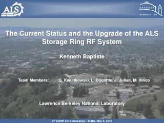
HVPS Upgrade for ALS Storage Ring RF System -Disconnect Switch Status May 10th 2012. S.Kwiatkowski LBNL ALS RF Group Contributors K.Baptiste , J. Julian. LBNL Advance Light Source.

E N D
HVPS Upgrade for ALS Storage Ring RF System -Disconnect Switch Status May 10th 2012 S.Kwiatkowski LBNL ALS RF Group Contributors K.Baptiste, J. Julian LBNL Advance Light Source
The new ALS storage ring RF system will use two 300kW THALES TH2161B klystrons to energize two single cell 500MHz ALS cavities. New systemwill require significant modification of the existing HV power supply (new power transformer, rectifier, choke and PLC based control). Also, classical ignitron based crow-bar system will be replaced with house made solid state disconnect switch which is undergoing final high power tests. We will keep existing voltage controlled unit based on 3-phase VVT which will regulate the DC voltage from 27kV to 54kV with precision better than +/- 0.5%. Our existing HVPS is rated at 56kV and 12A. Modify version will be rated at 54kV and 14.5A or 50kV and 16A (limited to 800kVA by VVT). LBNL Advance Light Source
Does existing crowbar system is giving adequate protection for klystron(s)? Philips YK1305 Requirements Fast switch-off of the beam PS has to be provided in following situations: 1. Beam current increase rapidly. 2. Solenoid current deviates by more than +/- 5% from nominal value. Proof protection: 28 gauge , 52cm long copper wire connected to the power supply instead of klystron should not be destroyed (approx. 60J -using I.M. Onderdonk Equation or 7.75kA for 10us pulse) Thales TH2161B Requirements Power supply must provide protection to limit energy discharge in the tube to 20J in case of arcing or too abrupt current surge. During resent testing of the ALS crowbar unit it was found that the ignitrons conducting time period is unpredictable and changes from few dozen to several hundreds of millisecond. The biggest danger for the protected equipment exist when the ignitrons stop conducting before the AC power is disconnected (~ 30ms) what has happened on two occasions (out of several dozen crowbar actions). In these cases power supply tried to build up very high voltage in the crowbar cabinet what resulted in discharges in protecting spark gap at approximately 70kV. No other damage has been done. LBNL Advance Light Source
Figure 1 If the PS is OFF and 6uF filter capacitor is fully charged, the wire test will not damage the wire (only 30J ). LBNL Advance Light Source
PSpice model of the existing HVPS with disconnect switch Figure 2 LBNL Advance Light Source
Voltage on the filter capacitor Figure 3 LBNL Advance Light Source
Figure 4 Figure 6 Fig. 4- represents the voltage on the filter capacitor(green) and filter choke(purple) during PS turn on. Fig.5- same voltages after nominal load disconnect action by IGBT disconnect switch. Fig.6- 19Hz and 720Hz ripples on the filter capacitor during PS operation on nominal load. V720Hz ~1Vp-p V19Hz ~7Vp-p Figure 5 LBNL Advance Light Source
How to take care of the turn-on, turn-off transients? Figure 7 LBNL Advance Light Source
Voltage on the filter capacitor and choke Figure 8 LBNL Advance Light Source
Fig.10 Current in the shorted load limited by 3mH inductor. Fig.9 26Hz and 720Hz ripples on the filter capacitor during PS operation on nominal load. V720Hz ~2Vp-p V26Hz ~8Vp-p LBNL Advance Light Source
Why Disconnect Switch? Generally, series switches have substantial advantages over the crowbars: Faster action (typically <3us versus 8-10us for crowbars) No stress on HV power supply elements. HV can be turn back on within microseconds. No series current limited resistors required. Simpler control circuitry No danger of mercury contamination. There are few companies like: Diversified Electronic Inc, North Star Research Corp or Polarity Inc, which are using IGBT technology to build high voltage, high current disconnect switches/modulators. We decided to design and build our disconnect switch. The main reason for this decision was lower cost and fast service by our staff . LBNL Advance Light Source
IGBT Choice In order to decrease the overall cost of the switch and decrease the power dissipation within the switch itself, we were looking for the IGBT with the high voltage handling capabilities and the small dissipation factor (forward voltage drop to opening voltage ratio). The new IXYS IXEL40N400 4kV, 40A, IGBT with the dissipation factor<0.1% and the price below $100, was by far the best choice. The ALS disconnect switch contains 24 4kV IGBT modules connected in series with the total voltage handling capabilities up to 72kV . This large excess voltage capability will create a large redundancy factor and increase its operational reliability since the switch could continue to operate even with several faulty IGBT modules. LBNL Advance Light Source
IGBT Data Sheet LBNL Advance Light Source
Balancing IGBT’s The static voltage balancing can be easily achieved by connecting in parallel with each IGBT resistor with the value which will create the current flow significantly higher than the leakage current of the worst solid state device in the chain. The dynamic unbalance conditions are created by unequal switching characteristics of the solid state device or unequal delay in the drive chains. The dynamic balance has been achieved in our switch by connecting 10nF ceramic capacitors across each IGBT output, plus delay chips in each IGBT drive chain. Each module has also internal protection against sudden overvoltage transient. It is accomplished by chain of 6 (500V ) transient suppressors connected between collector and gate of each IGBT. Protection works very well for up to multi microsecond overvoltage transients. LBNL Advance Light Source
Schematic Diagram of the 3kV IGBT Disconnect Switch Module Figure 11 LBNL Advance Light Source
3kV IGBT Disconnect Switch Module Figure 12 LBNL Advance Light Source
Figure 13 LBNL Advance Light Source
Disconnect switch view from front and back Figure 14 LBNL Advance Light Source
Disconnect Switch Test Set-Up Figure 15 LBNL Advance Light Source
50kV-PS Turn-On Short (Disconnect Switch Closed) Figure 16 LBNL Advance Light Source
50kV-PS Turn-On Short (Disconnect Switch Closed)-Trailing Edge Figure 17 LBNL Advance Light Source
Wire Test- PS at 50kV when shorted by 28Gage Wire Figure 18 LBNL Advance Light Source
Wire Test- PS at 50kV when shorted by 28Gage Wire-Front Edge Zoom Figure 19 LBNL Advance Light Source
CONCLUSIONS: So Far So Good 1.More Testing during two days shut-downs. 2. Plan-installation of the switch during second stage RF system upgrade (Early 2013) or even earlier to create ASAP better protection for THALES 2161B klystron. LBNL Advance Light Source