Download
1 / 20
200 likes | 326 Views
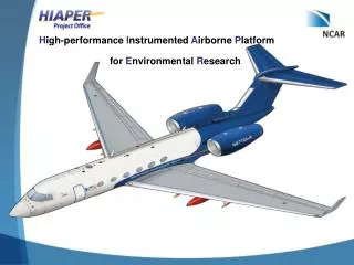
H igh-performance I nstrumented A irborne P latform. for E nvironmental R esearch. Actual Paint Scheme. GV Profile. Mission Capabilities Maximum Range : 6,055 nm (11,214 km) Maximum Cruise Altitude : 51,000 ft (15,545 m) Maximum Flight Duration : 13.9 hrs. Payload Capabilities

E N D
High-performance Instrumented Airborne Platform for Environmental Research
GV Profile Mission Capabilities Maximum Range: 6,055 nm (11,214 km) Maximum Cruise Altitude: 51,000 ft (15,545 m) Maximum Flight Duration: 13.9 hrs Payload Capabilities Max. Scientific Payload: 7,900 lbs (3,538 kg) Typical Scientific Payload: 3,300 lbs (1,497 kg) Max. Static Load per Wing Hard Point: 1,500 lbs (680 kg) Power and Signal Specifications Research Power: 115 VAC, 400 Hz single phase, 400 Hz 3 phase (cabin only), and 28 VDC (wings only) Signal Wiring: Analog, fiber optics, coax (video), twisted pair (serial)
Capabilities Comparison NSF/NCAR C-130 Red circle HIAPER (NSF/NCAR GV) Black circle NASA ER-2 Blue circle A comparison of maximum ranges of three U.S. research aircraft. The circles show the maximum distance to which each aircraft can fly from a base at Jefferson County Airport in Broomfield, CO (represented by the star) and return to the same base. Ranges shown correspond to flight of each aircraft at optimum altitude for ferry: 41,000 ft for HIAPER; 20,000 ft for NSF/NCAR C-130; 65,000 ft for NASA ER-2. Max. possible payload also deployed on each aircraft.
Research Speeds Mimimum Speeds
HIAPER Satcom System Block Diagram CockpitHandset Thales MCA-6010 Antenna Cockpit ICS CabinData Port #1 CabinData Port #2 IRU SDU HSU HPA SPZ-8500 CabinHandset #1 CabinHandset #3 CabinData Port #3 AFIS AirCell Transceiver Iridium Antenna VHF Blade Antenna Cabin ICS CabinHandset #2
Avionics & Communications Systems (ACS) Inc. equipment will be used by installer to match existing flight deck ICS/radio installation • HIAPER Features • 1-CAIU • 8-ACPs (Audio Control Panel) • 3 cockpit • 5 main cabin • ICP (Intercom Control Panel) • Baggage • 3 main cabin • Single channel only • ACP Broadcast/Receive - #1 VHF - SATCOM voice • 2-Net (channel) system
Planned Phase 1 Capabilities: June 2005 • Position & Ground Speed: GPS / IRU • Aircraft Attitude: IRU • Static Pressure: Single System • Air Speed: Redundant Systems • Altitude: GPS / IRU / Pressure Calculation • Ambient Temperature: Heated Reference • Absolute Humidity: Tropospheric Reference • 3-Dimensional Wind Field: Un-heated Radome • Aircraft Air Data Computer output is recorded: TAS, PALT, OAT, ATTACK, MACH#
Center Fuselage Locations – Diagram TOP VIEW FS 271.0 FS 346.0 FS 310.0 FS 421.8
Lower Fuselage Modification - Overview Center Fuselage Mount GVFS 270 Forward Fuselage Pads GVFS 82 Center Fuselage Mount GVFS 310 Center Fuselage Mounts GVFS 235 External Doubler Lower Optical Viewport GVFS 339 Lower Optical Viewport GVFS 290 Instrument Aperture Plates GVFS 250 HIAPER Lower Fuselage Penetrations
GV belly View Looking Aft
Lower Fuselage Modification Lower Fuselage Structure Center Fuselage Mount New keel members Modified Stringer 23 Center Fuselage Mount Instrument Aperture Plates Relocated O2 Bottles Lower Viewports
Inlet Apertures Apertures are 7” X 10”
HIAPER Research Electrical Systems • Research Power System • 115 VAC 400 Hz single phase • 115 VAC 60 Hz single phase (21 KVA total, 10.5 KVA per side) • 115/208 VAC 400 Hz 3 phase • 28 VDC Weight on Wheels (WOW) switched to wings only • All circuits (AC and DC) 20 amps • 10 secondary power distribution fuselage locations (2-60 Hz, 1- 400 Hz user, 1-400 Hz anti-ice (WOW) circuit(s) each location). • 8 Main Cabin • 1 Nose area • 1 Baggage
HIAPER Research Electrical Systems-Wing • Six Wing Hard Point locations • 2-115 VAC 60 Hz 20 A single phase circuits • 1-115 VAC 400 Hz 20 A single phase user circuit • 1-28 VDC 20 A circuit • Signal wires per hard point: • 8 analog (twinax) • 4-channel fiber • Three 9- and two 4-conductor cables • 2-100 Base T • 75/50 Ohm Coax
GV Interior Configuration Note: Seat locations shown are those at time of aircraft delivery to UCAR/NCAR. Seats can be removed and/or relocated according to the needs of each specific research program.
Air Flow/Trajectory Analyses Around the GV Fuselage Data presented was generated by Gulfstream and is proprietary. NCAR has CFD airflow data on/around the GV fuselage and wings and boundary layer depth. These data are archived at NCAR and can be viewed by investigators under NDA and by special arrangement. Please contact the HPO or EOL at NCAR. Analyses below generated for a GV flight speed of ~0.7 Mach (238 m/sec) at an altitude of approx. 40,000 - 45,000 ft.