Enterprise Modelling support to Knowledge Management
Enterprise Modelling support to Knowledge Management. Professor Guy Doumeingts Professor Emeritus University Bordeaux 1 General Manager INTEROP- VLab. Plan . INTEROP- Vlab Enterprise Modelling A case Study : how to improve the performance of a manufacturing system ? Conclusions.

Enterprise Modelling support to Knowledge Management
E N D
Presentation Transcript
Enterprise Modelling support to Knowledge Management Professor Guy Doumeingts Professor Emeritus University Bordeaux 1 General Manager INTEROP-VLab
Plan • INTEROP-Vlab • Enterprise Modelling • A case Study : how to improve the performance of a manufacturing system ? • Conclusions
Enterprise Interoperabilitydefinition “The ability of two or more systems or components to exchange information and to use the information that has been exchanged” (IEEE, 1990) “Capability of a system or a product to interact with other systems or products without specific effort from the user” (INTEROP-NoE definition May 2004) “ the ability of an enterprise system or application to interact with others at a low cost in a flexible approach (INTEROP-VLab definition, April 2007)”
I-VLab: the result of several years of EI development • Createdin March 2007, www.interop-vlab.eu • From the Network of Excellence INTEROP-NoE (Interoperability Research for Networked Enterprise Applications and Software, FP6 508011, 42 months, 50 partners, 12 M€ Budget, 6,5 M€ EC funds) • INTEROP-VLab is a non-profit international association under the Belgian Law (aisbl) • Grouping 9 regional poles, bringing together leading academics, research centers, industrial stakeholders, SMEs, from 11 European countries and from China,56 partners and more than 300 researchers
Missions To maintain and develop the defragmentation of the ERA (European Research Area) in cooperation with other regions of the world, in order: • To support the development of the research, education, innovation, standard in Enterprise Interoperability and associated domains as Enterprise Systems and Applications (ESA) and Application of Future Internet (AFI) • To be an Excellence Centre in the domain of Enterprise Interoperability and the associated domains at the world wide level
The INTEROP-VLab MemberPoles DFI e. V. Pole, Berlin (G), a German association, (Deutsches Forum für Interoperabilität), 8 partners INTEROP North Pole (Sweden, Norway, Finland), Helsinki (FI), a SIG*, repr. by University of Helsinki, 8 partners INTEROP-VLab UK Pole, Coventry (UK), a Limited without shares organization, repr. by TANet, 3 partners INTEROP-VLab China Pole, Harbin (Cn), a SIG*, represented by HIT, 15 partners Pole Grande Region (Lorraine, Belgium, Luxembourg), Nancy (FR), a SIG*, repr. by University Nancy Poincare, 4 partners GSO Pole (Grand Sud-Ouest), Bordeaux (F), a SIG*, repr. by Univ. Bordeaux 1, 17 partners INTEROP-VLab.IT Pole, Roma (IT), an Italian non-profit making scientific association, 7 partners Portuguese Pole, Lisbon (PT), a SIG*, repr. by UNINOVA, 4 partners INTERVAL Pole, Valencia (S), a Spanish non-profit association, 8 partners
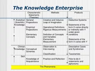
What is Enterprise Modelling? • The representation of activities of the enterprise according to different points of view : • Fonctions, Decisions, Processes, Information ..., • Technical, Economical, Social, Human, ..., • Under two interconnected views : • Global view : Concepts of system : objectives, structure, functionalities, evolution (dynamic), linked with the environment, • Local view : detailed description according to the concepts of activities and processes.
Developpement of Enterprise Modelling • Creation in States in 1980: ICAM Definition_ ICAM (Integrated Computer Aided Manufacturing) project (US AIR FORCE_DARPA)_ SADT_ • Three initial Methodologies: • IDEF0_IDEF 1_IDEF2 (ICAM Definition) now (Integrated Definition) • GRAI (1980) Graph with Results and Activities Interrelated) • PERA (1980) Purdue Enterprise Reference Architecture) • GERAM (1993) Generic Enterprise Reference Architecture and Methodologies: Result of a task Force: IFIP_IFAC • CIMOSA (1995) (Computer Integrated Manufacturing Open System Architecture) Result of European Project • BPM: Business Process Modeling (1995): ARIS • Our Conclusion: to model an Enterprise: • Concepts of System, • Formalisms: Function, Process, Information, Decision (Governance), Resources,
The GRAI model Control System / Controled System Objectives EXTERNAL INFORMATIONS CONTROL SYSTEM Controlactions Feedback { Suppliers Customers Purchasing Information Products Services { CONTROLED SYSTEM Customers
OBJECTIVES DECISION VARIABLES (DV) CRITERIA (FOR DV) CONSTRAINTS (ON DV) Control System The GRAI model External Information DECISION SYSTEM CUSTOMERS SUPPLIERS INFORMATION SYSTEM PRODUCTS SERVICES CUSTOMERS PHYSICAL SYSTEM ControlledSystem PURCHASING INFORMATION { DECISIONS = INFORMATIONS +
Design of New system Implementing improvements (ST, MT, LT) Manage evolution (indicators) GRAI® Structuredapproach Conceptualmodels of existing system Conceptualmodels of future system CONCEPTUAL LEVEL Information Objectives Information Decision Decision Physical Physical Process Process Functions Functions Modeling to understand and evaluate REALISATIONAL LEVEL Future system Existing system ST : Short Term MT : Medium Term LT : Long Term
Project board Define the objectives and the domain of the study Evaluate and valid the results Analysis &Validation Synthesis Group Specialist Main deciders (Realises a study) propose GRAI specialists and Analysts (Supports a study) propose Analysis &Validation Validation working groups (Working for solutions) Interviewees (Supply of Informations) Supply of Informations The actors
Board Group Synthesis Group Example of Study Planning The actors 3/4 months maximum 3/4 months maximum Modelling / Diagnosis Design Interviews Working Groups Double arrow = Framework
A real case Study : how to improve the performance of a manufacturing system?
Industrialcontext (1) Objectives of the study • Performance improvement of a Manufacturing S.M.E. belonging to a Group • Lead time are not respected • Financial situation veryserious • The context : • completere-engineering of the group • Difficult social situation • threestudies of re-organisation in last threeyears : no improvement
Industrialcontext (2) The production • The products : moulds for casting, containers for electronic, punch/tool, dies and complexassembly • The resources of production : 20 CNC machines, 60 conventional machines, CAD/CAM system, machine for the 3-dimensional control • Production order: • lead time of order : 1 to 6 weeks (average 4 to 6 weeks) • number of orders : 40 to 60 / month • verysmall batch • Existingfunctions : design, process, production, quality, commercial
Modelling phase (AS IS) (2) PLANNING PB2 24/8 p.m. PB1 8/ 6 PB SG I SG2 28/6 SG5 SG3 18/7 SG1 (15 / 6) SG4 24/8 a.m. Design phase diagnosis phase Modelling phase Double arrow = communication PB : Project Board SG : Synthesis Group I : Interviews 1 Meeting of Project Board 3 Meeting of Synthesis group 15 Interviews
Modelling phase (AS IS) (1) Presentation • Elaboration of a planning • Elaboration of Models : • Functional • Physical • Decisional • Pocesses • By a succession of: • Meetings of synthesis group • Interviews to collectKnowledge • Elaboration of Information Model
Modelling phase (AS IS) (3) Elaboration of the Models Functionalview, Physical System • using the formalism ACTIGRAMME, • the Models A-0, A0 are performed by the synthesis group, • the furtherdecompositions : A1, A2, ... A11, A23, .. A321, A422 are performed by INTERVIEWS. Important: to choose the intervieweeswith the synthesis group (safe of time). Criteria to stop : • To defineaccurately the objectives of the modelling : example : Functionalview : to understand the global behaviour of the SME. • To stop the decompositionwhenwethink to have sufficient information to reach the objectives.
Modelling phase (AS IS) (4) Elaboration of the Models • Decisional system: GRAI Grid :performedwith the Synthesis group GRAI Nets :performed by interviews Remark : the acquisition of informations by the GRAI Nets allowsto improvethe Grid. • Information System : In the study, by lack of time, the Information wasmodelledafter
Modelling phase (AS IS) (8) DECISIONAL SYSTEM : GRAI GRID V4
Modelling phase (AS IS)(9) DECISIONAL SYSTEM : GRAI NET
Modelling phase (AS IS) (10) Conclusion • The modelswerevalidated by the synthesis group at the meeting SG3. • Functional (version 2 or version 3) : A-0, A0, A1, A2, A3, A4, A5, A6 + one level of decomposition. • Physical system (version 2) : A-0, A0, A1, A2, A3, A4, A5, A6. • Decisional system : • GRAI Grid : version 4 • GRAI Net : 5 GRAI Nets
Diagnosis Phase (1) The meetings Meeting of the Synthesis Group SG4 : evaluation of the diagnosis phase • Listing of "points to improve" and strong points • Looking for solution tracks • Identification of Design constraints Meeting of the Project Board PB2 • validation of the diagnosisresultsevaluation • confirmation of design targets • validation of constraints
Diagnosis Phase(2) WorkingMethod The diagnosisisperformedfrom : • GRAI Rules for modelling • The knowledge of analysts • The knowledge of synthesis group members
Diagnosis Phase (3) Functionalview Role of the function "Scheduling" : all the pieces are goingthrough the function "Scheduling" • Important manualworkincreases the global cycle (time of transfert, waiting time, important products in progress) Function " Scheduling " : lot of activities of different nature (scheduling, logistic, maintenance…) difficult to improvetogether ActivityBid - Preparation : not accurateevaluation of the lead time • difficulties to plan
Diagnosis Phase (4) Physical System All the parts have to go through the Scheduling All the parts have to go through the control • increase the producting cycle and increase the costs • wrong circulation of the physical flow Evaluation of some performance indicators : • Ratio of flow tension (Horizon of the production / Total operative times for one unit of the finishedproducts) • Number of the orders' delay • Distance of transportation of products • Rate of inventory turnover
Diagnosis Phase (5) Physical System Organisation in job-shop of production in comparison to an organisation by load centre Strong points : • Excellent ability of operators • Quality products Questions : • Reduction of products number regarding enterprise strategy ? • Relationships with commercial department (evaluation of lead time)
Diagnosis Phase (6) Decisional System : global model Lack of planning at long term level : • no anticipation and no evaluation of the consequences on the capacity and supply • the management of the purchasing and of the subcontracting make is made at short term : no optimisation • lack of information from commercial department and few follow up • no integration between the functions of the system
Diagnosis Phase (7) Decisional System : global model Lack of planning at medium term level : • difficulties to adapt the capacity to the load • no synchronisation with the other functions • commercial : information on the situation to the load • preparation : validation of lead time • to manage products : to evaluate the implications of the delivery delays • to manage resources : to anticipate the overloads or sub-loads
Diagnosis Phase (8) Decisional System : detailed model (Nets) • Majority of eventdrivendecisions : few anticipation • Few action meansat medium term (PL20 et PL40) • Few criteria for the decisionmaking (cost, lead time) • Good capacity of adaptation and flexibility (short term)
Conclusions of the Diagnosis Phase(9) Points to improve • Lackof decisions for anticipation at medium and long terms • Action Means and flexibility are badusedbecause of the short term system troubles • Lackin the cost and lead time master • Concept of contract not enoughused Strong Points • High adaptation and reactivity • Good technicalskills • High level of productquality
Design phase of target system (TO BE) (1) • 6 solutions tracks 1 - Studyof physical flow. 2 - Reorganisation of service "Scheduling". 3 - Implementation of a system planning. 4 - Strategic and commercial actions. 5 - Definition of procedures for the Quality control . 6 - Methodological and supports software tool for the preparation
Design phase of target system (TO BE) (2) Planning PB3 (4/11) PB SG WG SG5 (31/8) SG6 (22/9) SG7 (20/10) SG8 (16/11) DESIGN PHASE PB : Project Board SG : Synthesis Group WG : Working Group (6 groups) Double arrows = decision frame
Design phase of target system (TO BE) (3) • Hierarchical planning system implementation
Design phase of target system (TO BE) (4) Decisional System
The action plan • A set of concrete actions such as :
CONCLUSIONS on the study On the study • Exemplary study • Top management involvement • Actors involvement • Action planning On the performance • Turn over increase : 10% • Customer service level improvement • Number of firm orders / Number of quotation in increase
Questions on the interest of the approach • Enterprise Modelling is very complex and not efficient: is it true now? • The method could replace a consultant? How? In which condition? • The collected knowledge could be reuse for the next evolution? • The collected knowledge can be considered as a “MAP” to help to determine the continuous evolution of the enterprise ? • This Knowledge is the equivalent of the knowledge concerning the design of a part? • This knowledge is inside the head of the people of the enterprise : do we need a Knowledge Keeper and not a consultant? Last comment: :the employees of the enterprise They know problems and have ideas for solutions: they need to be supported in a structured way
Conclusions • Concreteexample of use of Enterprise Modelling • Possibility to combine with ECOGRAI (methodology to define and implement Performance Indicators ) (developped in cooperationwith KAPLAN (Harvard), father of BSC( Balanced Score Card) • Use of EM in Servitization (MSEE: ManufacturingSErviceEcosystem) EC Project • Use of EM for Supply Chain System(cooperationbetweenEnterprises) or for ECOSYSTEM