Download
1 / 33
330 likes | 463 Views
Direct measurement of the transverse long-range wake-field of the CLIC main linac accelerating structure G . De Michele 1,2,3 , E . Adli 1,4 , A . Grudiev 1 , A . Latina 1 , D . Schulte 1 , W . Wuensch 1 1 CERN , 2 PSI, 3 EPFL , 4 The University of Oslo. W. Wuensch

E N D
Direct measurement of the transverse long-range wake-field of the CLIC main linac accelerating structure G. De Michele1,2,3, E. Adli1,4, A. Grudiev1, A. Latina1, D. Schulte1, W. Wuensch1 1CERN, 2PSI, 3EPFL, 4The University of Oslo W. Wuensch SAREC review meeting 30-31 January 2012
Motivation • The main performance issues for the CLIC main linac accelerating structures are: • Accelerating gradient • Wakefields and higher-order-mode suppression • rf-to-beam efficiency • (The three issues are marvelously interconnected) • The performance of the accelerating structures drives the efficiency and cost of CLIC. • We dedicate significant resources to demonstrate high-gradient performance.
High-gradient testing At KEK and at SLAC Status end 1011 Break down rate scaled to 100 MV/m, CLIC pulse
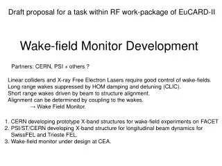
Motivation 2 We now propose an experimental program to investigate long-range wakefields. Why? Do we expect surprises? Well no, but… Wakefields , and specifically higher-order-mode suppression, is probably being computed very accurately. But we’re currently close to beam dynamics limits and as we push the design towards lower cost we will depend on the accuracy of the simulations more and more. Also accelerating structures are complex objects, for example with lots of silicon carbide loads. The only experimental verification of a waveguide damped wakefields was in ASSET in late 1999 – we feel it is essential to check our latest design, material choice etc. Finally the wakefield measurement is a concrete exercise for our beam dynamics team and their tools. It can only be healthy for those dealing with wakefields in simulation to deal with them in a real machine.
There is a long tradition of measuring accelerating structure wakefields in ASSET
1. GLC/NLC Exp vs Cct Model Wake Qcu DS ASSET Data RDDS1 DDS3 (inc 10MHz rms errors) DDS1 H60VG4SL17A/B -2 structure interleaved RDDS1 Conspectus of GLC/NLC Wake Function Prediction and Exp. Measurement (ASSET dots) Refs: 1. R.M. Jones,et al, New J.Phys.11:033013,2009. 2. R.M. Jones et al., Phys.Rev.ST Accel. Beams 9:102001, 2006. 3. R.M. Jones, Phys.Rev.ST Accel. Beams, Oct.,2009. 6
150 cells/structure, 15 GHz Higher-order mode damping demonstration in ASSET 1999 Then Now Double band circuit model 24 cells/structure, 12 GHz (loads not implemented yet) An Asset Test of the CLIC Accelerating Structure, PAC2000
The CLIC baseline structure Hs/Ea Es/Ea Sc/Ea2
Wakefield simulations • Different EM codes have been used to simulate the wake-fields in the CLIC RF prototype with dispersive materials: GdfidL, CST Particle Studio®, ACE3P • Different materials (i.e. different EM properties) have been tested in order to meet the beam dynamics requirements CST: superPC, 128 GB of RAM and 24 CPUs GdfidL: distributed and shared memory Transverse wake-field
The predicted wake-field Three main dipolar bands in the Impedance spectrum Transverse real impedance 2nd bunch Transverse wake-field Absolute value of the envelope of the transverse wake
What we need from measurements • Roll-off speed to be confirmed up to 0.25m • Wake-field threshold • Identification of frequencies from wake-field measurements: high sampling of the wake-fields with the witness bunch Roll-off threshold
Critical issue for simulation in time domain: dispersive materials • GdfidL • The permittivity can be expressed with an N-th order Lorentz medium with resonant angular frequencies ωn and damping angular frequencies γn: • This feature has been debugged in late 2011! • CST 2012 version • the transient solver has undergone many improvements, in particular with respect to, e.g., broadband constant loss tangent. The broadband sensitivity analysis with respect to geometry and material property variation has also been enhanced. 4th order Lorentz medium
Wakefield measurements of the CLIC baseline accelerating structure in ASSET/FACET
Why FACET? • Possibility of having driving and witness bunches with positrons and electrons. • Adjustable bunch spacing for a timing span behind the driving bunch. • Bunch length flexibility: ideally shorter than 1mm in order to resolve the 3rd dipole band which shows up a peak around 40GHz. POSSIBLE LOCATION Layout of the ASSET facility
Where in FACET LI02 sector ASSET CLASSE
Young people from the CLIC study (not me) are becoming familiar with the linac and the wakefield measurement
Experimental procedure The transverse wake-field can be extrapolated from the measurements of the deflecting angle of the witness bunch active length of the structure energy of the witness bunch transverse wakefield Transverse wakefield drive bunch charge drive bunch offset witness charge drive bunch length witness bunch length
Experiment simulations with tracking code PLACET A. Latina G. De Michele • BPMs upstream and downstream of the structure are needed in order to determine the bunch offset in the structure, as well as dipole corrector magnets to generate this offset. • only BPMs downstream of correctors are sensitive to the correction itself. That means that the lattice response is triangular. Response matrix from the south extraction kicker in SRD to LI02
Positrons: offset scan to drive wakefield The BPMs just before and after the RF prototype are LI02, 201 and LI02, 211. The correctors used are only two upstream these two BPMs. With only two correctors seems possible to shift the positron beam in the RF prototype. To be verified the maximum voltage that can be applied to the correctors.
Electrons: Deflected by wakefield • We can compute the witness bunch deflections from betatron oscillation fits to data from the BPMs downstream of the test structure, and corrected for incoming orbit jitter using the results from similar fits to data from BPMs in the NRTL line [C. Adolphsen et al., PRL 74 13, 1995] • For the fit of trajectory parameters, one needs the knowledge of BPM locations and lattice parameters, i.e. quantities which have no stochastic errors. For the fit of lattice parameters, however, one has to correlate BPM data with trajectory parameters, i.e. quantities which will in general have significant stochastic noise components. In this case, the fit must take into account the noise on the measured trajectory parameters due to finite BPM resolution [SLAC-CN—371]. • Once we have simulated all the experiment with the tracking code PLACET, our routines will be Interfaced with the SLAC Control Program (SCP). Hopefully in March 2012 first tests.
BPMs resolution From the experiment proposal: • An accurate data analysis is required • Good knowledge of the optics is essential • Orbit fit to determine the kick
Lattice simulations and verification in 2012 run • The experiment can be reproduced numerically with all imperfections. Data acquisition as well as data analysis can be simulated. • From the physical point of view the experiment can be completely simulated. • We have only deal with technical problems and software integration on SCP.
The test structure – a simplified assembly since the dipole mode Q’s are low
FACET prototype scheme • six TD26 accelerating structures • simple vacuum tank • no power will be sent to the test structure and the double feed couplers will be terminated by the loads • clamped aluminum cells • available length: 76.80 inches vacuum vacuum vacuum flange bellow pump pump vacuum tank transition beam pipe 1.5m 76.80 inches main strongback in the ASSET area Support and alignment system
CLIC accelerating structure for ASSET A. Solodko BEAM Reference spheres Ø180mm AS Aluminium disks AS AS AS Cell shape accuracy 20µm AS TD26 with Compact Couplers (x6), clamped AS Features for Tank alignment on the girder Damping material (SiC) Aluminium disk Features for AS alignment in the Tank 6 sections, 24 cells each, compact coupler design Clamped aluminum disks To be tested at SLAC Clamp for SiC fixation Threaded rod for AS clamping
Mechanical design: features • Uses existing vacuum tank • Estimated total load of the CERN installation is about 400 kg • Two vacuum ion pumps (noble diode pumps, 53-55 l/s) • The RF structure is aligned mechanically inside the vacuum tank • The vacuum tank will be aligned to the beam axis by means of adjustable feet (drawings needed) • Two tooling balls on both ends are present on top of the vacuum tank
What full prototype cells look like Machining: OFHC copper diamond milled and turned disks with micron precision. G. Riddone, S. Atieh +- 5 micron tolerance lines
Mechanical design: dimensions • Available longitudinal space 76.80inches • RF structure disks diameter: 180mm • RF structure longitudinal dimensions: 6 X 250mm • Beam pipe: 1inch outer diameter • Vacuum flanges: 2 ¾ inches • Distance between beam-pipe center to main strongback: 8.795inches • Accelerating cell inner radius: 2.35mm
Coordination with FACET runs(may already be obsolete) • 2012 - CLIC personnel participate in linac measurements in preparation for wakefield measurements. • 2013 - After commissioning of positrons, we have two options: • Re-measure the installed DDS then install the CLIC RF structure • Install and measure only the CLIC RF structure • But in any case the CLIC RF structure will be ready for September 2012.