Download
1 / 36
370 likes | 483 Views
Process modeling. BCIS 4610. Agenda. Proposals due Guest speaker Accreditation video DFD review and HW2 discussion Process modeling with BPMN HW2 discussion continued. Jason Benfield, Seilevel.

E N D
Process modeling BCIS 4610 BCIS 4610
Agenda • Proposals due • Guest speaker • Accreditation video • DFD review and HW2 discussion • Process modeling with BPMN • HW2 discussion continued BCIS 4610
Jason Benfield, Seilevel • Business Architect and GM of the DFW area for Seilevel, a professional services organization based out of Austin. • Seilevelconsultants operate as Business Architects, Product Managers, and Business Analysts within Fortune 1000 companies. BCIS 4610
Next few classes • Oct 3 – Conceptual data modeling • HW2 is due • Oct 10 – Moving into design. Architecture design. Midterm exam review. • HW 3 is due • Oct 17 – Midterm exam • Oct. 24 – Logical data modeling. • Interim report due BCIS 4610
HW 2 • HW 2 – needs to be completed in Visible Analyst. • For Minicase 2 in Ch. 5 (p. 219-220) • (a) Create a context-level DFD • (b) Create a Level-0 DFD • (c) Create a use-case description for processing staffing requests in the placement department. • (d) Create a process map for processing staffing requests in the placement department. BCIS 4610
Moving from planning to analysis • Overview of Core Business Processes • NPV analysis • Project ID • Project Management Intro • Effort Estimation • Critical Path Analysis • Project Proposal and Plan • Collecting user requirements • Use case analysis • Process modeling BCIS 4610
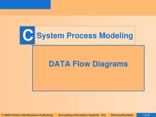
Data Flow Diagram (DFD) • A picture of the movement of data between external entities and the processes and data stores within a system • Difference from system flowcharts: • DFDs depict logical data flow independent of technology • Flowcharts depict details of physical systems BCIS 4610
Naming and Drawing DFD Elements Process Data flow Data store External entity BCIS 4610
A defining the boundaries, inputs and outputs of the system with a context-level DFD BCIS 4610
Breaking a system into subsystems and showing the flow of data among them with a Level-0 DFD BCIS 4610
Relationship among Levels of DFDs Context diagram Level 0 diagram Level 1 diagram Level 2 diagram BCIS 4610
Validating the DFD • Syntax errors – diagram follows the rules • Assure correct DFD structure • For each DFD check each process for: • A unique name: action verb phrase; number; description • At least one input data flow • At least one output data flow • Output data flow names usually different thaninput data flow names • Between 3 and 7 processes per DFD BCIS 4610
Validating the DFD For each DFD:Check each data flow for:A unique name: noun; description Connects to at least one process Shown in only one direction (no two-headed arrows) A minimum number of crossed lines Check each data store for: A unique name: noun; description At least one input data flow At least one output data flow Check each external entity for: A unique name: noun; description At least one input or output data flow BCIS 4610
Validating the DFD Across DFDs:Context Diagram:Every set of DFDs must have one Context DiagramViewpoint:There is a consistent viewpoint for the entire set of DFDsDecomposition:Every process is wholly and complete described by the processes on its children DFDsBalance: • Every data flow, data store, and external entity on a higher level DFD is shown on the lower level DFD that decomposes it • No data stores or data flows appear on lower-lever DFDs that do not appear on their parent DFD BCIS 4610
Process Modeling BCIS 4610
Requirements Modeling Techniques • Process/flow modeling technique • Activity diagram • Data flow diagram • Event identification • Flowchart • Sequence diagram • State machine diagram • Workflow models (Process maps) BCIS 4610
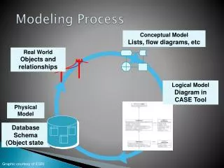
Definition of a process • A process – is a series of value added tasks that are linked together to convert inputs into a product or service into an output. Output Inputs Process BCIS 4610
Process modeling: Workflow diagrams BCIS 4610
Workflow Diagrams/Process Maps/ Flowcharts • A workflow model is a visual representation of the flow of work in a business area. Workflow models are used to document how work processes are carried out, and to find opportunities for process improvement. • Purpose - Workflow models are used to depict the sequential flow of a work process. • A workflow model represents: • business activities, • the sequentialflow of these activities, • the persons who perform the work, • key business decisions that affect the flow of work, and • the start and end points of the process flow. BCIS 4610
MS Visio notations BCIS 4610
Strengths and weaknesses • Strengths • Ability to visually represent complex flows with multiple decision points and parallel flows • Easy to develop and easily understood by most audiences • Support the identification of problems and alternative solutions • Can show a workflow across the enterprise, or within one functional area • Weaknesses • Multiple sets of diagramming conventions (ANSI/ISO, UML, IDEF3, BPMN etc.) BCIS 4610
Business Process Modeling Notation (BPMN) • The (BPMN) is a standardized graphical notation for drawing business processes in a workflow. • BPMN was developed by Business Process Management Initiative (BPMI), and is now being maintained by the Object Management Group since the two organizations merged in 2005. Its current adopted version is 1.1 and the proposed one is 2.0. • The primary goal of BPMN is to provide a standard notation that is readily understandable by all business stakeholders. BCIS 4610
Key elements • Activities/Tasks: rounded rectangles show the individual steps or pieces of work that must be completed in order to execute the business process. • Sequence (control) flows: arrows indicate the direction of the step by step sequence of the workflow. • Gateways • Exclusive (decision points) diamond shapes show forks where the flow of work proceeds in two or more mutually exclusive flows and, optionally, where separate flows merge together. • Inclusive (forks and joins) diamond with a cross or solid bars indicate branch points where the flow of work proceeds in two or more parallel paths which subsequently join together again. • Swim-lanes: horizontal or vertical divisions indicate responsibility for performance of the activities. • Events: symbols indicating the start, end and intermediate events of the flow. BCIS 4610
We will use the following notations • Activity • Start End • Sequential flow • Decision point • Join • Swim lanes BCIS 4610
An example of a simple business process BCIS 4610
Modeling process patterns BCIS 5120
Process Modeling Patterns BCIS 5120
Process modeling patterns BCIS 5120
Let us draw a process for making a reservation • What is the trigger? • What are the key roles? Are they within or outside of the organization? • What are the key activities? • What are the key inputs and outputs? • What are the decisions that need to be made? BCIS 4610