Download
1 / 45
460 likes | 747 Views
Smart Antenna Array technology utilizes digital signal processing to adaptively transmit and receive signals, enhancing capacity, coverage, and link quality in wireless networks, radar, electronic warfare, and satellite systems. With features like switched lobe and dynamically phased arrays, these systems offer interference rejection and improved signal tracking capabilities, outperforming conventional antennas.

E N D
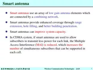
Smart Antenna Array: • antenna array with a digital signalprocessing capability to transmit and receive in an adaptive and spatiallysensitive manner. • “Smart” >>digital signal processing facility
USAGE • Applications to: • cellular and wireless networks • radar • electronic warfare (EWF) as a countermeasure to electronic jamming • satellite systems
WHY SMART ANTENNA ARRAYS? • Higher Capacity • Higher Coverage • Higher bit rate • Improved link quality • Spectral efficiency • Mobility
Pave Paws phased array antenna Long range VHF radar for detection of ICBMs
A/N SPY-1 phased array radar antenna
Phased array using slotted elements Flat panel is scanned mechanically
Elements of a Smart Antenna number of radiating elements a combining/dividing network control unit
Aim : • to maximize the antenna gain in the desired direction • to minimize the gain in directions of interferers
Switched lobe (SL): ( also called “switched beam” ) simplest technique comprises only a basic switching function between separate directive antennas or predefined beams of an array
Top View Top View Antenna Array Antenna Conventional Antennas & Arrays Omnidirectional Sectorized
Active Beam Desired User Antenna Array Interfering User Antenna Array WHY SMART ANTENNA ARRAYS ARE SUPERIOR TO CONVENTIONALANTENNAS Switched Beam System Adaptive Array
Dynamically phased array (PA): continuous tracking can be achieved by including a direction of arrival (DoA) algorithm for the signal received from the user can be viewed as a generalization of the switched lobe concept
Dynamically phased array (PA): • A generalization of the switched lobe concept • The radiation pattern continuously track the designated signal (user) • Include a direction of arrival (DoA) tracking algorithm
Interference Rejection Comparison Desired Signals Co-channel Interfering Signals
Switched beam antennas • Based on switching function between separate directive antennas or predefined beams of an array • Space Division Multiple Access (SDMA) = allocating an angle direction sector to each user • In a TDMA system, two users will be allocated to the same time slot and the same carrier frequency • They will be differentiated by different direction angles
Polarization Diversity . • For polarization diversity horizontal and vertical polarization is used • Can only double diversity gain • Polarization diversity is known to be effective in urban areas
Angle Diversity • which implements different beam patterns on the different antennas • This combination results in a higher overall gain pattern • Allows the same 120 sectored base station support more users by changing the degree of separation
One Dimensional Phased Array • Simplest phased array is a linear (1-D) array • Elements are in a straight line, spaced d wavelengths apart • Element spacing d must be in range 0.5 to 1.0 wavelengths • Used to create Omni directional antennas with a narrow beam in the vertical plane
Beam-steering using phase shifters at each radiating element d 3 2 0 Beam Steering Beam direction Equi-phase wave front = [(2/)d sin] Radiating elements Phase shifters Power distribution
Dipoles with uniform phase Broadside beam Fig 10.26 Omni directional dipole array Transmitted RF wave is vertically polarized
Dipoles with progressive phase shift Phase 0o Beam is depressed to improve coverage of ground 10o 20o 30o 40o Fig 10.27 Omni directional dipole array Transmitted RF wave is vertically polarized 25
Fig 10.28 Series Fed Linear Array wavefront Beam direction wavelets T dipoles T T T T load Equal time delays
Cellular Phone Base Station Antennas • Cell phone base stations use linear array antennas like the one shown in Fig. • The linear array makes a narrow beam in the horizontal plane that is tilted down a little for best coverage over the earth’s surface • Directional elements can be used to make the beam cover a sector • Cell phone towers with a large number of antennas are covering several frequency bands and providing sector coverage to increase the number of users
Cell phone tower with sector and Omni antennas. Small dishes link tower to cell phone HQ and other towers.
Fig 10.32 Parallel Fed Linear Array wavefront Beam direction T wavelets dipoles Progressive time delays T T T T Splitters
Beam Steering • Beam is steered by changing relative phase between elements • Fixed time (phase) delays give fixed beam • Cell phone tower antenna has fixed beams • Electronically controlled phase shifter gives movable beam • Used mainly in military radars because of high cost • Elements must be excited with correct amplitude distribution to control sidelobes
Beam Steering • Relative phasing between elements determines beam direction • Analyze for transmit case … apply reciprocity for receive • Consider case of two adjacent elements • One element has phase shift 0o • Adjacent element has phase shift • Beam direction is to the array normal where = (2/) d sin
Fig 10.33 Setting Beam Angle Beam angle Broadside x d 0o x = d sin = (2 / ) d sin d
Beam Steering • Example #1: Steer beam to 30o from normal (broadside) • Element spacing d = 0.6 • = (2 / ) d sin • = 2 x 0.6 x sin 30o • = 1.2 x ½ = 0.6 = 108o • We must insert 108o phase shift between elements
Fig 10.34 Parallel fed linear array scanned 30o Beam direction 30 degrees 108o wavefronts Phase Shifts in degrees 0 108 216 324 Splitters
Beam Steering • Example #2: Steer beam to 45o from normal • Element spacing d = 0.6 • = (2 / ) d sin • = 2 x 0.6 x sin 45o • = 1.2 x ½ = 0.848 = 153o • We must insert 153o phase shift between elements
Fig 10.35 Linear array scanned 45o Beam direction 45 degrees 153o wavefronts Phase shifts in degrees 0 153 306 99 Splitters
Using CDMA with Smart Antenna Technology • In CDMA systems all cells use the same carrier frequency. Users are distinguished by their different codes. • The number of users within one cell is limited mainly by the interference that each user generates for all other users. • By pointing the main beam of the adaptive antenna pattern to the desired user, smart antennas improve the SNIR for one user without increasing interference for the other users. • Note that even an increase of the capacity by only a factor 2 is highly desirable, since it means that twice as many customers can access the network
SDMA (Space Division Multiple Access) more than one user can be allocated to the same physical communications channel simultaneously in the same cell separated by angle only in a TDMA system, two users will be allocated to the same time slot and carrier frequency at the same time and in the same cell