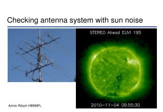
Checking Antenna Systems
Learn about ideal antenna systems at 50 ohms, reflected power, SWR formulas, equipment for measuring SWR, and how to troubleshoot high SWR issues. Get insights on using SWR meters, Bird Wattmeters, and Antenna Analyzers efficiently. Discover the relevance of couplers in controlling antenna systems. Real-world scenarios and practical solutions provided.

Checking Antenna Systems
E N D
Presentation Transcript
Checking Antenna Systems WB5CXC
Energy Transfer • You get maximum energy transferred when all impedances are the same. • Normally the two items that are fixed are the transmitter (50 ohms) and the coax (comes in different impedances – normally 50 ohms) • The antenna will change impedance with a frequency change. Can be complex impedance (resistance and reactance).
Reflected Power • If the end of the transmission line is Open or Shorted – no power is dissipated by the load (there isn’t any load). • All power will be reflected back. • The transmission line will absorb some due to the loss in the line. • We usually measure the reflected power and refer to it as Standing Wave Ratio (SWR).
(Positive Number) Standing Wave Ratio (SWR) - Formulas
10% Reflected Power Impedance Ration 2:1 Modern Transceiver SWR Limitation – SWR < 2 (Less than 10% power reflected OR 25 – 100 ohms)
Equipment for Measuring SWR • SWR Meter • Need to measure Forward & Reflected Power & not just SWR • Bird Wattmeter (need proper slug) • Antenna Analyzer • Other Specialized equipment • Each type has their place and use. You will probably end up with several of these.
SWR Meters • Older types - you have to set the forward reading to a calibration setpoint, then read the SWR • Newer types have double needle meter showing Foreword & Reflected Power (usually different scales), read SWR on another scale. • Automatic double needle meters and SWR meters.
Notice the different scales – Forward power 300 watts, reflected 50 watts
Bird Wattmeter • Power Meter that has slugs (Frequency & Power). Turning the slugs enables it to read Foreword & Reflected Power. • You compute SWR. • Bird Wattmeter was the standard for commercial radio departments for years. • Requires different slugs for the different frequency & power (i.e. 300 – 400 Mhz 10w)
Bird 43 Wattmeter Bird 43 Wattmeter Slugs Notice the arrow. Notice the direction arrow.
Antenna Analyzer • They use a low power signal generator. Signal is sent to the cable and the analyzer computes the values of R, Z, SWR. • By adjusting the analyzer frequency you can tell how far off resonance you are, and if the antenna needs to be shorter or longer.
RF-1 Analyzer MFJ Analyzer
Fixed Station Antenna Analyzer • Computer connected antenna analyzer that do many things and are laboratory grade instrumentation. Standalone for limited indications. • They are a little expensive but within the price of amateur radio.
Coupler Controller LP-100A Antenna Analyzer
Problems with High SWR • Most modern transistor transceivers now have protection against high SWR. They will limit the output so the finals are protected. Most transceivers start limiting the output at SWR of 2. • High SWR reduces the amount of energy that is radiated from the antenna.
Practical Problem • You are measuring a 440 Mhz repeater, it has 475 feet of 7/8” foam coax. • Bird Wattmeter read 45 watts forward and 4.49 watts reflected. Good or Bad
Analysis of Problem • The antenna lead has snapped off at the antenna. • 100% of signal is reflected • The line has a loss of 1.02 dB/100 feet. • Total loss of the line is 1.02 dB X 4.75 = 4.98 dB (5 dB). • What is the reflected power at the top of the line?
Analysis of Problem cont’d • 5 dB = 3.16 loss (approximately 1/3 of the power at the top) • 45 watts * 1/3.16 = 14.22 watts • This is reflected back down the line. • 14.22 * 1/3.16 = 4.49 watts (loss back down) • Line is BAD (open at the antenna) • Can’t just look at the SWR !!!! SWR = 1.92
Real Story • An Ham bought an antenna and he had an high SWR he tried to adjust it but couldn’t get it to come down within SWR < 2. • Wrote to manufacturer and they said you need at least 75’ of RG-58 and then the antenna will be good. • Add more loss to system makes the antenna have less SWR.
XXXX • Some