Download
1 / 19
200 likes | 265 Views
Understand lead-acid battery operation, components, failure modes, and simulations using Randles circuit model. Learn about electrochemistry, capacitance, and state of health parameters.

E N D
LEAD ACID BATTERY MODELINGIEEE ESSB Summer 2016 Meeting Frank X. Garcia 12 June 2016
Presentation Objectives • Explain lead acid cell operation at the atomic level • Present a Randles circuit model approximation of a lead acid cell • Examine computer simulations trending using Randles circuit model
Outline • Battery Overview • Components • Electrochemistry • Double layer capacitance • State of health parameters • Randles circuit model • Single cell approximation • Failure modes analysis • Computer Simulations
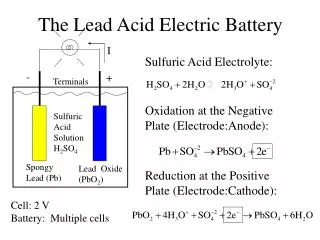
Battery Components • A battery is an energy storage device • Converts chemical energy into electrical energy during a discharge, and can also • Store electrical energy during a recharge • The major components of a lead acid battery include: • CATHODE-terminal post connected to the positive plates • ANODE- terminal post connected to the negative plates • NEGATIVE PLATES - lead grids filled with pure, spongy Pb • POSITIVE PLATES -lead grids filled with PbO2 • ELECTROLYTE- aqueous conductor of ions between the negative and positive plates, H2SO4 with H20 • (38% concentration of sulfuric acid) • SEPARATOR- non-conductive material that separates the negative and positive plates and prevents them from shorting
Electrochemistry New electrodes inserted into electrolyte -Anode Cathode + -Anode Cathode + Pb0 PbO2 H2O H2O H+ H+ SO4-2 H+ H+ H+ H2O SO4-2 - - H+ H+ SO4-2 SO4-2 H+ - - H2O H+ H+ H+ H+ Pb+2 SO4-2 H2O H2O SO4-2 Pb+2 Reduction Oxidation
Electrochemistry Reduction Pb+4 +2O-2(s) +4H+(aq) + SO4-2(aq) + 2e- PbSO4(s) +2H2O(aq) Energy released E0 = 1.69 eV Vcell= 1.69V – (-0.36V) = 2.05V -Anode Cathode + @ T = 25C H2O H+ H2O - - H+ SO4-2 - - H2O H+ H+ Pb+2 SO4-2 H2O SO4-2 Pb+2 Double Layer Capacitances Diffusion Layer s* 1.69V * Discussed Later 0V Oxidation Pb(s) + SO4-2(aq)PbSO4(s) + 2e- Energy released E0 = -0.36 eV -0.36 V
Electrochemistry Charge Cycle: Electrochemical process is reversed Discharge Cycle Vcell - + - I Iload H2O - - H2O - - H2O H+ H+ SO4-2 Pb+2 SO4-2 SO4-2 H+ H+ Pb+2 H2O Reduction Oxidation
Double Layer Capacitance • Ions adsorbed to the surface of the electrode held by electrostatic force • Positive ions too large to penetrate electrode metal surface • Only electrons can travel through the metal conduction bands • Solvated ions encapsulated by water molecules can migrate through diffusion layer • A second layer of solvated ions create the outer layer forming capacitive double layer • Double layer has an ionic density gradientwhich allow Ionic migration in the diffusion layer • Bulk region maintains an equal concentration of electrolyte
State of Health Parameters • Float voltage • Set to recommended range for optimal battery life • Life expectancy decreases as float voltage increases • Float current • A high float current indicates aging battery • Negative post temperature • Indefinite 10oC temperature rise decrease battery life by 50% • Electrolyte Specific Gravity • Sulfuric acid (H2SO4) concentration can indicate state of charge • Fully charged: 1.26 to 1.3 specific gravity • Admittance/Impedance/Resistance Trending • Admittance will decrease as the battery ages • Impedance and Resistance will increase as battery ages
Randles Circuit Model Simplification Step 1 Ignore Cbulk since its magnitude is much larger than Cdl- and Cd+ Step 2 Add the series resistances Rm+, Rm- and Rbulk Step 3 Add the 2 voltage potentials - 1.69V +0.36V = 2.05V
Randles Circuit Model Simplification Note 1 Most models in the literature combine the half-cell circuits resulting in Cdl_eq, Rct_eq and Zdiff_eq Note 2 Many models in the literature often ignore Zdiff
Randles Circuit Parameters Progression Randles circuit parameters progression over the cell lifetime or discharge
Computer Simulations • Strategy • Examine degradation of a cell using complete Randles Circuit Model • Simulate Nyquist plots of baseline, +20% and +40% impedance due to cell aging • Synthesize component values to determine parametric changes • Circuit Model (one cell)
Computer Simulations • Nyquist Plots • Baseline impedance: 1 • +20% Impedance: 2 • Component Synthesis 1 2 Zim 5kHz 0.001 Hz Zre * C – constant of the Warburg element, - constant phase of the Warburg element
Computer Simulations • Nyquist Plots • Baseline impedance: 1 • +40% Impedance: 2 • Component Synthesis 1 2 Zim 5kHz 0.001 Hz Zre * C – constant of the Warburg element, - constant phase of the Warburg element
Summary • Randles circuit model approximates electrochemistry of a lead acid cell • Simplified Randles circuit model reduces analysis accuracy • Trending in Randles element values add visibility to battery state of health • Baseline immitance using Discrete Frequency Immitance Spectroscopy • Synthesize Randles circuit model battery elements • Analyze battery degradation by comparing element value changes from a known reference