Download
1 / 39
390 likes | 423 Views
Develop a scalable, open architecture robotic platform for education, research, and competitions. Interchangeable modules, remote control, and adaptable design features.

E N D
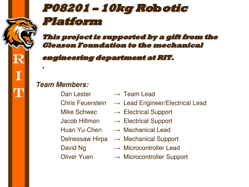
P08201 – 10kg Robotic PlatformThis project is supported by a gift from the Gleason Foundation to the mechanical engineering department at RIT.. Team Members: Dan Lester → Team Lead Chris Feuerstein → Lead Engineer/Electrical Lead Mike Schwec → Electrical Support Jacob Hillmon → Electrical Support Huan Yu-Chen → Mechanical Lead Delnessaw Hirpa → Mechanical Support David Ng → Microcontroller Lead Oliver Yuen → Microcontroller Support
Agenda • Introduction – 10 minutes • Mechanical Subsystems – 20 min • Platform Design – 10 minutes • Drive System Design – 10 minutes • Electrical Subsystem – 20 minutes • Systems Overview – 3 minutes • Motor Controller (H-bridge) – 10 minutes • Battery Monitor – 7 minutes • Microcontroller Subsystem – 15 minutes • Feedback/Q&A – 25 minutes
Project Description • The mission of this family of projects, within the Vehicle Systems Technology Track, is to develop a land-based, scalable, modular open architecture, open source, fully instrumented remote/controlled vehicular platform for use in a variety of education, research & development, and outreach applications within and beyond the RIT KGCOE. • This student team will re-design two modular, fully functional robotic platforms capable of carrying a payload anywhere in the robotics lab, room #9-2230 in Building #09 on the RIT campus. • One drive platform shall be three wheeled, with at least one motor module, and a payload capacity of at least 2.5kg. • The second drive platform shall have at least four wheels, with at least two motor modules, and a payload capacity of 10kg. • Each platform will be required to accomplish two tests as stated in the PRP.
Customer Needs • The platform performs testing requirements • Impressive looking for high school students in the US FIRST robotics competition. • Interchangeable modules (at least one) within 120 seconds • Scalable with 100kg (with expectations to scale down to 1kg) • Adaptable for other senior design projects • Robot must be able to be controlled remotely
Rectangular Configuration Length: 26.75 inches Width: 27.0 inches Height: ~21.0 inches (without payload)
Triangular Configuration Length: 24.0 inches Width: 23.0 inches Height: ~19.0 inches (without Payload)
New Chassis Structure • Made of inexpensive, strong, lightweight acrylic tubing • Easy assembly – members are joined with epoxy, and screw
Modular Motor Mounts • Easily mounts motor modules to chassis • Modules fixed in rails with two thumbscrews • Adding or removing modules is quick and easy • Made of inexpensive, easy to machine plastics
New Motor Design Concept • Focus on easy assembly, low center of gravity, shorten the overall height New Old
2:1 Motor Module • Axle design has low ground clearance and large turning radius and restriction for infinite rotation • Steering Motor torque restriction 2:1 Axle 2:1 Belt
1:1 Motor Module Design • Flat design allows for infinite rotation • Low Design significant lower the center of gravity, however it’s rotation is restricted by the wiring. Flat Low
Risk Analysis of Mechanical Components • Clear Acrylic Tubing • Load Carrying Capability • Bending of Members • Impact Resistance • Scratching / Weathering / Cracking • Epoxy • Alignment of Members • Cleanliness upon Application • Fatigue over time • Complete Failure under Loading / Operation • Motor Mount Thumb Screw • Vibration under Operation • High Density Polyethylene (HDPE) Motor Mounts • Flexing under loading
Computer System • Requirements: • 6 PWM Channels • UART Communication • Total of 46 I/O ports • Input: 30 Ports • Output: 10 Ports
Remote Control System • Go with our ultimate goal of having wireless communication
Laptop (Wireless) • Pros: Wireless; Functionality; Durability; • Cons: Complexity; Security; Cost
Hardware Overview of wireless modules chosen: - Crossbow TelosB (TPR2420) - Crossbow MICAz (MPR2400) Overview of microcontroller chosen: - PIC PIC18F8722
Crossbow TelosB • Features: • Runs TinyOS • Long Battery Life • USB Port for Programming and/or Communication 802.15.4 Compatible • 48 KB Flash Memory • 4KB EEPROM • 10 KB RAM • TX Rate: 250 kbps • Indoor Range: 20 m – 30 m • Specifications: • Module Size (in) 2.55 x 1.24 x 0.24 • Power Input: 2x AA Batteries
Crossbow MICAz • Features: • 2.4 GHz transceiver • Based on TinyOS • Provides inherent data security (AES-128) • USB Port for Programming and/or Communication • 128 KB Flash Memory • 4KB EEPROM • UART • TX Rate: 250 kbps • Indoor Range: 20 m – 30 m • Specifications: • Module Size (in) 2.25 x 1.25 x 0.25 • Power Input: 2x AA Batteries
Pin-out Diagram (MICAz) Atmega128L
PIC PIC18F8722 • Features: • Inexpensive • Provides sufficient PWM channels (5 modules: 4 chans) • Provides sufficient I/O ports (70) • 10 MHz Processing Speed • 128 KB Flash Memory • 4 KB RAM • 1KB EEPROM • USART (RS232 & RS485) • RS232 Communication • Specifications: • Module Size (in) 82mm x 62 mm x 25 mm • Power Input: 5 Vdc
Pin-out Diagram (PIC) Ports: A – G (6), J Input: 2 Ports Output: 4 Ports
Software • Workstation: VMWare • Environment: XubunTOS (Xubuntu + TinyOS 2.0 Debian packages) • Programming Languages: C, nesC
Senior Design I – Next Steps • Fall Quarter Week 8 – Detail Design Review • Fall Quarter Week 10 – Final Presentation for SD1 • Spring Quarter Week 1 – Initial implementation of design concepts obtained from SD1


