Download
1 / 25
250 likes | 281 Views
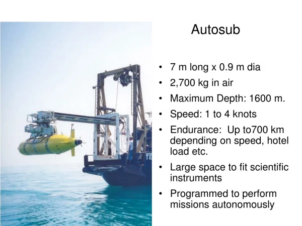
This detailed guide covers all aspects of Autosub mission planning, preparation, initiation, execution, and post-mission operations. It includes equipment details, safety considerations, control modes, and future developments.

E N D
Autosub Mission Planning and Operations Dr. Miles Pebody Ocean Engineering Division Southampton Oceanography Centre M.Pebody@soc.soton.ac.uk
Overview • Equipment • Pre-Mission Planning • Mission Preparation and Initiation • Mission End and Post Mission
Equipment: Computing Resources • Three Networked PCs • Mission programming, mission management and vehicle telemetry. • Acoustic Tracking • Data Processing Tershelling April 2000
Equipment: On Surface Communications • Lonworks VHF Radio Modem (range 0.5Km) • Ethernet VHF Radio Modem (range 0.5Km) • Orbcomm Satellite Communications • Argos Satellite Tracking
Equipment: Subsurface Communications • 23-33KHz Acoustic Tracking, Telemetry and Commands • 10-14KKz Tracking (telemetry in development)
Pre-Mission Planning • Mission Requirements • Mission Navigation • Control Modes • Autosub Safety Issues • The Mission End - Recovery
Mission Requirements • Instruments/sensors • Data sampling • Area of operation • Vehicle critical factors • Power availability • Depth ratings
Mission Navigation • Waypoint selection • Co-ordinate System • Cartesian (X/Y metre offset) • Polar (latitude/longitude) • Navigation Mode Selection • Heading only • Heading to position • Follow track between two positions Example: track of 110 km mission off Fort Lauderdale. Coast, Florida.
Control Modes: Depth/Altitude Control Depth control Altitude control - terrain following Autosub can also be programmed to profile Up/Down at constant pitch angles
Mission Safety Issues • In water obstacles • Terrain - vehicle pitch control • Surfacing zones • Mission depth and altitude limits • Emergency abort timeouts
Mission Preparation and Initiation • Mission Script • Configuration Script • Mission Script Checking • Pre-Launch Tasks • Post-Launch / Pre-Start Tasks
Mission Simulation Warnings Radio Modem Down-loader Mission Compiler History File Go! Stop Mission Commander + Monitor Operations: Mission Preparation Mission Script Editor Configuration Editor Control parameters Sensor parameters Safety limits EAS timers + limits
Operations: The Mission Script // When satisfactory GPS fix has been acquired dive and track follow: // Set timeout to 500 seconds. WHEN( GotGPSfix) // When GPS fix acquired ……… Timer( 500), // Set timeout of 500 seconds. Depth( 10), // Set depth mode to 10 metres. MotorPower( 400), // Set motor mode to Power 400 Watts. PositionP( N:56:27.5, W:5:29.4); // Set position mode and demand // Next line, when reached end of the track …… WHEN( GotPosition) // When Got there (OR timeout) ………
Now we use a gantry system. Operations: The Launch • Early launches through ship’s ‘A’ Frame.
Operations: Monitoring unattended missions Orbcommdata link Text messageon cell phone GPS Orbcomm GPSposition Status message Terschelling Autosub campaign March 00
Mission End: Autosub Relocation. • Local ARGOS tracking to horizon • Surface radio telemetry within 0.5 Km • Acoustic Telemetry within 1 Km (soon 6Km) • Acoustic tracking within 8 Km
Mission End and Post Mission • Logger Data Recovery • Autosub Recovery • Navigation Postprocessing and Engineering data examination
The End Dr. Miles Pebody Ocean Engineering Division Southampton Oceanography Centre M.Pebody@soc.soton.ac.uk
Autosub Systems: Navigation • GPS or DGPS fixes on the surface update the position estimate. • Special Navstar GPS antenna overcomes problems of washover on tail mounted antenna. • Broadcast (300 kHz) DGPS corrections used. • Uses RDI 300kHz Doppler sonar (250 m range) for velocity.& Seatex MRU6 compass for rotation into earth co-ordinates. • Biggest problem is heading dependent compass errors. • Errors can be substantially reduced to about 0.5-1% of distance travelled with calibration. • Calibration involves a short box mission.
Autosub Systems: Heading Control Modes of Operation. • Heading • Line Of Sight - (Head towards demanded Waypoint). • Track Follow - (Follow Straight Line Track Between Two Waypoints).
Future Developments • Integrated mission planning tools including mission simulation and replay. • Modify Mission Control and Emergency Abort for the more complex environment of under-ice missions. • Power source - fuel cells, semi-fuel cells. • Improved Collision Avoidance in the horizontal plane. • Improved Navigation. Use Ring Laser Gyro based INS. From 1% to 0.1% of distance traveled. • Improved Acoustic Communications and Location.