Download
1 / 38
630 likes | 1.27k Views
ECONOMIC AND PRODUCT DESIGN CONSIDERATIONS IN MACHINING. Machinability Tolerances and Surface Finish Selection of Cutting Conditions Product Design Considerations in Machining. Machinability.

E N D
ECONOMIC AND PRODUCT DESIGN CONSIDERATIONS IN MACHINING • Machinability • Tolerances and Surface Finish • Selection of Cutting Conditions • Product Design Considerations in Machining
Machinability Relative ease with which a material (usually a metal) can be machined using appropriate tooling and cutting conditions • Depends not only on work material • Type of machining operation, tooling, and cutting conditions are also important factors ©2002 John Wiley & Sons, Inc. M. P. Groover, “Fundamentals of Modern Manufacturing 2/e”
Machinability Criteria in Production • Tool life – how long the tool lasts for the given work material • Forces and power – greater forces and power mean lower machinability • Surface finish – better finish means better machinability • Ease of chip disposal – easier chip disposal means better machinability ©2002 John Wiley & Sons, Inc. M. P. Groover, “Fundamentals of Modern Manufacturing 2/e”
Machinability Testing • Most tests involve comparison of work materials • Performance of a test material is measured relative to a base material • Relative performance is expressed as a machinability rating (MR) • MR of base material = 1.00 (100%) • MR of test material > 1.00 (100%) means better machinability ©2002 John Wiley & Sons, Inc. M. P. Groover, “Fundamentals of Modern Manufacturing 2/e”
Machinability Tests • Tool life (most common test) • Tool wear • Cutting force • Power required in the operation • Cutting temperature • Material removal rate under standard test conditions ©2002 John Wiley & Sons, Inc. M. P. Groover, “Fundamentals of Modern Manufacturing 2/e”
Mechanical Properties that Affect Machinability • Hardness • High hardness means abrasive wear increases so tool life is reduced • Strength • High strength means cutting forces, specific energy, and cutting temperature increase • Ductility • High ductility means tearing of metal as chip is formed, causing chip disposal problems and poor surface finish ©2002 John Wiley & Sons, Inc. M. P. Groover, “Fundamentals of Modern Manufacturing 2/e”
Tolerances and Surface Finish in Machining • Tolerances • Machining provides high accuracy relative to most other shape-making processes • Closer tolerances usually mean higher costs • Surface roughness in machining is determined by: • Geometric factors of the operation • Work material factors • Vibration and machine tool factors ©2002 John Wiley & Sons, Inc. M. P. Groover, “Fundamentals of Modern Manufacturing 2/e”
Geometric Factors • Machining parameters that determine surface geometry: • Type of machining operation, e.g., milling vs. turning • Cutting tool geometry, especially nose radius • Feed • The surface geometry that would result from only these factors = "ideal" or "theoretical" surface roughness ©2002 John Wiley & Sons, Inc. M. P. Groover, “Fundamentals of Modern Manufacturing 2/e”
Effect of Nose Radius ©2002 John Wiley & Sons, Inc. M. P. Groover, “Fundamentals of Modern Manufacturing 2/e”
Effect of Feed ©2002 John Wiley & Sons, Inc. M. P. Groover, “Fundamentals of Modern Manufacturing 2/e”
Effect of End Cutting Edge Angle ©2002 John Wiley & Sons, Inc. M. P. Groover, “Fundamentals of Modern Manufacturing 2/e”
Ideal Surface Roughness where Ri = theoretical arithmetic average surface roughness; f = feed; and NR = nose radius ©2002 John Wiley & Sons, Inc. M. P. Groover, “Fundamentals of Modern Manufacturing 2/e”
Work Material Factors • Built‑up edge effects • Damage to surface caused by chip • Tearing of surface when machining ductile materials • Cracks in surface when machining brittle materials • Friction between tool flank and new work surface ©2002 John Wiley & Sons, Inc. M. P. Groover, “Fundamentals of Modern Manufacturing 2/e”
Effect of Work Material Factors ©2002 John Wiley & Sons, Inc. M. P. Groover, “Fundamentals of Modern Manufacturing 2/e”
To Predict Actual Surface Roughness • First compute ideal surface roughness value • Then multiply by the ratio of actual to ideal roughness for the appropriate class of work material ©2002 John Wiley & Sons, Inc. M. P. Groover, “Fundamentals of Modern Manufacturing 2/e”
Vibration and Machine Tool Factors • Related to machine tool, tooling, and setup: • Chatter (vibration) in machine tool or cutting tool • Deflections of fixtures • Backlash in feed mechanism • If chatter can be eliminated, then surface roughness is determined by geometric and work material factors ©2002 John Wiley & Sons, Inc. M. P. Groover, “Fundamentals of Modern Manufacturing 2/e”
How To Avoid Chatter (Vibration) • Add stiffness and/or damping to setup • Operate at speeds that avoid cyclical forces with frequencies close to natural frequency of machine tool system • Reduce feeds and depths to reduce forces • Change cutter design to reduce forces • Use a cutting fluid ©2002 John Wiley & Sons, Inc. M. P. Groover, “Fundamentals of Modern Manufacturing 2/e”
Selection of Cutting Conditions • One of the tasks in process planning • For each operation, decisions must be made about machine tool, cutting tool(s), and cutting conditions • These decisions must give due consideration to workpart machinability, part geometry, surface finish, and so forth • Cutting conditions: speed, feed, depth of cut, and cutting fluid ©2002 John Wiley & Sons, Inc. M. P. Groover, “Fundamentals of Modern Manufacturing 2/e”
Selecting Depth of Cut • Depth of cut is often predetermined by workpiece geometry and operation sequence • In roughing, depth is made as large as possible to maximize material removal rate, subject to limitations of horsepower, machine tool and setup rigidity, and strength of cutting tool • In finishing, depth is set to achieve final part dimensions ©2002 John Wiley & Sons, Inc. M. P. Groover, “Fundamentals of Modern Manufacturing 2/e”
Determining Feed • In general: feed first, speed second • Determining feed rate depends on: • Tooling – harder tool materials require lower feeds • Roughing or finishing ‑ Roughing means high feeds, finishing means low feeds • Constraints on feed in roughing ‑ Limits imposed by cutting forces, setup rigidity, and sometimes horsepower • Surface finish requirements in finishing – select feed to produce desired finish ©2002 John Wiley & Sons, Inc. M. P. Groover, “Fundamentals of Modern Manufacturing 2/e”
Optimizing Cutting Speed • Select speed to achieve a balance between high metal removal rate and suitably long tool life • Mathematical formulas are available to determine optimal speed • Two alternative objectives in these formulas: • Maximum production rate • Minimum unit cost ©2002 John Wiley & Sons, Inc. M. P. Groover, “Fundamentals of Modern Manufacturing 2/e”
Maximum Production Rate • Maximizing production rate = minimizing cutting time per unit • In turning, total production cycle time for one part consists of: • Part handling timeper part = Th • Machining timeper part = Tm • Tool change time per part = Tt/np , where np = number of pieces cut in one tool life ©2002 John Wiley & Sons, Inc. M. P. Groover, “Fundamentals of Modern Manufacturing 2/e”
Maximum Production Rate Total time per unit product for operation: Tc = Th + Tm + Tt/np Cycle time Tc is a function of cutting speed ©2002 John Wiley & Sons, Inc. M. P. Groover, “Fundamentals of Modern Manufacturing 2/e”
Cycle Time vs. Cutting Speed ©2002 John Wiley & Sons, Inc. M. P. Groover, “Fundamentals of Modern Manufacturing 2/e”
Minimizing Cost per Unit • Inturning, total production cycle cost for one part consists of: • Cost of part handling time = CoTh , where Co = cost rate for operator and machine • Cost of machining time = CoTm • Cost of tool change time = CoTt/np • Tooling cost = Ct/np , where Ct = cost per cutting edge ©2002 John Wiley & Sons, Inc. M. P. Groover, “Fundamentals of Modern Manufacturing 2/e”
Minimizing Unit Cost Total cost per unit product for operation: Cc = CoTh + CoTm + CoTt/np +Ct/np Again, unit cost is a function of cutting speed, just as Tc is a function of v ©2002 John Wiley & Sons, Inc. M. P. Groover, “Fundamentals of Modern Manufacturing 2/e”
Unit Cost vs. Cutting Speed ©2002 John Wiley & Sons, Inc. M. P. Groover, “Fundamentals of Modern Manufacturing 2/e”
Comments on Machining Economics - I • As C and n increase in Taylor tool life equation, optimum cutting speed should be reduced • Cemented carbides and ceramic tools should be used at speeds significantly higher than for HSS • vmax is always greater than vmin • Reason: Ct/np term in unit cost equation pushes optimum speed to left in the plot of Cc vs. v ©2002 John Wiley & Sons, Inc. M. P. Groover, “Fundamentals of Modern Manufacturing 2/e”
Comments on Machining Economics - II • As tool change time Tt and/or tooling cost Ct increase, cutting speed should be reduced • Tools should not be changed too often if either tool cost or tool change time is high • Disposable inserts have an advantage over regrindable tools because tool change time is lower ©2002 John Wiley & Sons, Inc. M. P. Groover, “Fundamentals of Modern Manufacturing 2/e”
Product Design Guidelines in Machining - I • Design parts that need no machining • Use net shape processes such as precision casting, closed die forging, or plastic molding • If not possible, then minimize amount of machining required • Use near net shape processes such as impression die forging ©2002 John Wiley & Sons, Inc. M. P. Groover, “Fundamentals of Modern Manufacturing 2/e”
Product Design Guidelines in Machining - II • Reasons why machining may be required: • Close tolerances • Good surface finish • Special geometric features such as threads, precision holes, cylindrical sections with high degree of roundness ©2002 John Wiley & Sons, Inc. M. P. Groover, “Fundamentals of Modern Manufacturing 2/e”
Product Design Guidelines in Machining - III • Tolerances should be specified to satisfy functional requirements, but process capabilities should also be considered • Very close tolerances add cost but may not add value to part • As tolerances become tighter, costs generally increase due to additional processing, fixturing, inspection, sortation, rework, and scrap ©2002 John Wiley & Sons, Inc. M. P. Groover, “Fundamentals of Modern Manufacturing 2/e”
Product Design Guidelines in Machining - IV • Surface finish should be specified to meet functional and/or aesthetic requirements • However, better surface finish generally increases processing cost by requiring additional operations such as grinding or lapping ©2002 John Wiley & Sons, Inc. M. P. Groover, “Fundamentals of Modern Manufacturing 2/e”
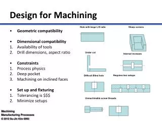
Product Design Guidelines in Machining - V • Machined features such as sharp corners, edges, and points should be avoided • They are difficult to machine • Sharp internal corners require pointed cutting tools that tend to break during machining • Sharp corners and edges tend to create burrs and are dangerous to handle ©2002 John Wiley & Sons, Inc. M. P. Groover, “Fundamentals of Modern Manufacturing 2/e”
Product Design Guidelines in Machining - VI • Machined parts should be designed so they can be produced from standard stock sizes • Example: rotational parts with outside diameters equal to standard bar stock diameter ©2002 John Wiley & Sons, Inc. M. P. Groover, “Fundamentals of Modern Manufacturing 2/e”
Product Design Guidelines in Machining - VII • Select materials with good machinability • As a rough guide, allowable cutting speed and production rate correlates with machinability rating of a material • Thus, parts made of materials with low machinability take longer and cost more to produce ©2002 John Wiley & Sons, Inc. M. P. Groover, “Fundamentals of Modern Manufacturing 2/e”
Design machined parts with features that can be produced in a minimum number of setups • Example: Design part with geometric features that can be accessed from one side of the part • Figure 24.6 – Two parts with similar hole features: • holes that must be machined from two sides, requiring two setups, • and holes that can all be machined from one side ©2002 John Wiley & Sons, Inc. M. P. Groover, “Fundamentals of Modern Manufacturing 2/e”
Product Design Guidelines in Machining - VIII Machined parts should be designed with features that can be achieved with standard cutting tools • Avoid unusual hole sizes, threads, and features requiring special form tools • Design parts so that number of individual cutting tools needed is minimized ©2002 John Wiley & Sons, Inc. M. P. Groover, “Fundamentals of Modern Manufacturing 2/e”