Network Layer
Computer Networks. Network Layer. 4.1 Introduction 4.2 Virtual circuit and datagram networks 4.3 What is inside a router? 4.4 IP: Internet Protocol Datagram Format IPv4 addressing Subnets CIDR ARP & DHCP NAT. 4.5 Routing algorithms Algorithm Classification Link State

Network Layer
E N D
Presentation Transcript
Computer Networks Network Layer
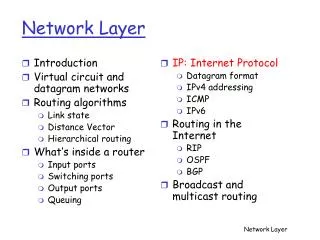
4.1 Introduction 4.2 Virtual circuit and datagram networks 4.3 What is inside a router? 4.4 IP: Internet Protocol Datagram Format IPv4 addressing Subnets CIDR ARP & DHCP NAT 4.5 Routing algorithms Algorithm Classification Link State Distance Vector Hierarchical Routing 4.6 Routing in the Internet RIP OSPF BGP 4.7 ICMP Network Layer Topics K & R Computer Networks Network Layer
Network Layer Introduction • Concerned with getting packets from source to destination. • The network layer must know the topology of the subnet and choose appropriate paths through it. • When source and destination hosts are in different networks, the network layer (IP) must deal with these differences. • Key issue: What service does the network layer provide to the transport layer? connection-orientedor connectionless Computer Networks Network Layer
Network Layer Design Goals 1. The services provided by the network layer should be independent of the subnet topology. 2. The transport layer should be shielded from the number, type and topology of the subnets present. 3. The network addresses available to the transport layer should use a uniform numbering plan (even across LANs, WANs and WLANs). Computer Networks Network Layer
Network Layer Messages Messages Segments Transport layer Transport layer Network service Network service Network layer Network layer Network layer Network layer End system b End system a Data link layer Data link layer Data link layer Data link layer Physical layer Physical layer Physical layer Physical layer Leon-Garcia & Widjaja: Communication Networks Computer Networks Network Layer
Network Layer Machine B Machine A Application Application Transport Transport Router/Gateway Internet Internet Internet Network Interface Network Interface Network Interface Network 1 Network 2 Leon-Garcia & Widjaja: Communication Networks Computer Networks Network Layer
Metropolitan Area Network (MAN) Organization Servers Gateway To the Internet or wide area network s s Backbone R R R S Departmental Server S S R R R s s s s s s s s s Leon-Garcia & Widjaja: Communication Networks Computer Networks Network Layer
Wide Area Network (WAN) Interdomain level Border routers Internet Service Provider (ISP) Autonomous system or domain Border routers LAN level Intradomain level Leon-Garcia & Widjaja: Communication Networks Computer Networks Network Layer
Modern Internet Backbone National service provider A National service provider B NAP NAP National service provider C Network Access Point National Internet Service Providers Leon-Garcia & Widjaja: Communication Networks Computer Networks Network Layer
Network Access Point NAP RA RB Route server LAN RC often called the default router Leon-Garcia & Widjaja: Communication Networks Computer Networks Network Layer
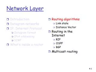
4.1 Introduction 4.2 Virtual circuit and datagram networks 4.3 What is inside a router? 4.4 IP: Internet Protocol Datagram Format IPv4 addressing Subnets CIDR ARP & DHCP NAT 4.5 Routing algorithms Algorithm Classification Link State Distance Vector Hierarchical Routing 4.6 Routing in the Internet RIP OSPF BGP 4.7 Broadcast and multicast routing Network Layer Topics K & R Computer Networks Network Layer
Datagram Packet Switching Packet 1 Packet 1 Packet 2 Packet 2 Packet 2 Leon-Garcia & Widjaja: Communication Networks Computer Networks Network Layer
Datagram Routing Table Output port Destination address 0785 7 1345 12 IP addresses 1566 6 2458 12 Leon-Garcia & Widjaja: Communication Networks Computer Networks Network Layer
Virtual Circuit Packet Switching Packet Packet Leon-Garcia & Widjaja: Communication Networks Computer Networks Network Layer
Virtual Circuit Routing Table Output port Next identifier Identifier 12 44 13 Entry for packets with identifier 15 Packet leaves with new identifier 23 15 9 23 27 13 16 58 7 34 Leon-Garcia & Widjaja: Communication Networks Computer Networks Network Layer
network data link physical network data link physical network data link physical network data link physical network data link physical network data link physical network data link physical network data link physical network data link physical network data link physical network data link physical application transport network data link physical application transport network data link physical Network Layer • transports segment from sending to receiving host. • encapsulates segmentson sending side into datagram packets. • delivers segmentson receiving side to the transport layer. • network layer protocols exist in every host, router. • router examines header fields in all IP datagrams passing through it. K & R Computer Networks Network Layer
4.1 Introduction 4.2 Virtual circuit and datagram networks 4.3 What is inside a router? 4.4 IP: Internet Protocol Datagram Format IPv4 addressing Subnets CIDR ARP & DHCP NAT 4.5 Routing algorithms Algorithm Classification Link State Distance Vector Hierarchical Routing 4.6 Routing in the Internet RIP OSPF BGP 4.7 ICMP Network Layer Topics K & R Computer Networks Network Layer
Two Key Network Layer Functions analogy: • forwarding: process of getting through single interchange • routing: process of planning trip from source to destination • forwarding:move packets from router’s input to appropriate router output. • routing:determine route taken by packets from source to destination. K & R Computer Networks Network Layer
routing algorithm local forwarding table header value output link 0100 0101 0111 1001 3 2 2 1 value in arriving packet’s header 1 0111 2 3 Interplay between Routing and Forwarding Routing creates thetables. Forwarding uses the tables. K & R Computer Networks Network Layer
Router Node Forwarding node15 Routing table lookup 134 17 packet packet 17 IncomingLink Outgoing Link Server Router Link Buffer Computer Networks Network Layer
Routing in an internet Figure 3.14 A Simple internetwork with Three Routers Computer Networks Network Layer
Protocol Layers along the Route • IPruns on all the nodes in a collection of networks and defines the infrastructure that allows these nodes and networks to function as a single logical internetwork. Figure 3.15 Protocol Layers used for a Simple internet Computer Networks Network Layer
Forwarding Table Example Table 3.6 Complete Forwarding Table for Router R2 in Figure 3.14 Note – As R2 is on Network 2 and Network 3, this table shows packets headed for H1, H2 and H3 are not forwarded by R2 to another router. Computer Networks Network Layer
ICMP protocol • error reporting • router “signaling” • IP protocol • addressing conventions • datagram format • packet handling conventions • Routing protocols • path selection • RIP, OSPF, BGP forwarding table The Internet Network Layer Host, router network layer functions: Transport Layer: TCP, UDP Network Layer Data Link Layer Physical Layer K & R Computer Networks Network Layer
4.1 Introduction 4.2 Virtual circuit and datagram networks 4.3 What is inside a router? 4.4 IP: Internet Protocol Datagram Format IPv4 addressing Subnets CIDR ARP & DHCP NAT 4.5 Routing algorithms Algorithm Classification Link State Distance Vector Hierarchical Routing 4.6 Routing in the Internet RIP OSPF BGP 4.7 ICMP Network Layer Topics K & R Computer Networks Network Layer
IP protocol version number 32 bits total datagram length (bytes) head. len type of service header length (bytes) ver length fragment offset Three fields for fragmentation/ reassembly flgs 16-bit identifier TOS:: data type upper layer time to live header checksum TTL:: max hops remaining (each router decrements) 32 bit source IP address upper layer protocol to deliver payload to 32 bit destination IP address Options (if any) E.g. timestamp, record route taken, specify list of routers to visit. data (variable length, typically a TCP or UDP segment) IPv4 Datagram Format how much overhead with TCP? • 20 bytes of TCP • 20 bytes of IP • = 40 bytes + app layer overhead K & R Computer Networks Network Layer
network links have MTU (max.transfer size) - largest possible link-level frame. different link types, different MTUs large IP datagram divided (“fragmented”) within net one datagram becomes several datagrams. “reassembled” only at final destination. IP header bits used to identify, order related fragments. IP Fragmentation & Reassembly fragmentation: in: one large datagram out: 3 smaller datagrams reassembly K & R Computer Networks Network Layer
IP Fragmentation & Reassembly Specified in 8 byte units Figure 3.18 Header fields used in IP fragmentation: (a) unfragmented packet; (b) fragmented packets. Computer Networks Network Layer
IP Fragmentation for Figure 3.14 Figure 3.17 IP datagrams traversing the sequence of physical networks graphed in Figure 3.14. Computer Networks Network Layer
4.1 Introduction 4.2 Virtual circuit and datagram networks 4.3 What is inside a router? 4.4 IP: Internet Protocol Datagram Format IPv4 addressing Subnets CIDR ARP & DHCP NAT 4.5 Routing algorithms Algorithm Classification Link State Distance Vector Hierarchical Routing 4.6 Routing in the Internet RIP OSPF BGP 4.7 Broadcast and multicast routing Network Layer Topics K & R Computer Networks Network Layer
Global Internet NSFNET backbone Stanford ISU BARRNET MidNet ■ ■ ■ regional Westnet regional regional Berkeley PARC UNL KU UNM NCAR UA Figure 4.1 The tree structure of theInternet in 1990 Computer Networks Network Layer
Global Internet • Each provider network is regional and a single autonomous system (AS) • Major issues are: • Scalability of routing • Address utilization • Now out of IPv4 addresses • Hierarchy is used to improve scalability. • Namely, utilize subnets with masks. Computer Networks Network Layer
IPv4 Network Classes Figure 3.19 IP addresses: (a) class A; (b) class B; (c) class C. Computer Networks Network Layer
Network Number Problems • Assigning one network number per physical network uses up IP address too fast! • Adding more network numbers also increases forwarding table size. Subnet solution :: • The idea is to take a single IP network number and allocate the IP addresses with that network number to several physical networks which are referred to as subnets. • The subnets need to be physically close to each other for routing purposes. Computer Networks Network Layer
Subnetting • The mechanism by which a single network number can be shared among multiple networks involves configuring all the nodes on each subnet with a subnet mask. • The subnet mask enables introduction of a single subnet number which provides for another level of hierarchy into the IP address. • All hosts on a given subnet are configured with the same mask, i.e., there is one subnet mask per subnet. Computer Networks Network Layer
IP address:: 32-bit identifier for host, router interface. interface:: connection between host/router and physical link router’s typically have multiple interfaces. host typically has one interface. IP addresses are associated with each interface. 223.1.1.2 223.1.3.2 223.1.3.27 223.1.3.1 223.1.2.1 223.1.2.2 IP Addressing: Introduction 223.1.1.1 223.1.2.9 223.1.1.4 223.1.1.3 223.1.1.1 = 11011111 00000001 00000001 00000001 223 K & R 1 1 1 Computer Networks Network Layer
IP address: subnet part (high order bits) host part (low order bits) What is a subnet ? device interfaces with same subnet part of IP address. can physically reach each other without an intervening router. Subnets 223.1.1.1 223.1.2.1 223.1.1.2 223.1.2.9 223.1.1.4 223.1.2.2 223.1.1.3 223.1.3.27 subnet 223.1.3.2 223.1.3.1 network consisting of threesubnets K & R Computer Networks Network Layer
Subnet Masks Figure 3.20 Subnet Addressing Computer Networks Network Layer
Subnetting Example Figure 3.21 An Example of Subnetting Table 3.7 Forwarding Table at Router R1 Computer Networks Network Layer
Subnet Concepts To determine the subnets, detach each interface from its host or router, creating islands of isolated networks. Each isolated network is called a subnet. Sending host does bitwise AND between subnet mask and destination address to determine whether packet needs to be routed or not. 223.1.1.0/24 223.1.2.0/24 223.1.3.0/24 Subnets Subnet mask: /24 :: defined bythe leftmost 24 bits. K & R Computer Networks Network Layer
How many subnets in the figure? Subnets 223.1.1.2 223.1.1.1 223.1.1.4 223.1.1.3 223.1.7.0 223.1.9.2 223.1.9.1 223.1.7.1 223.1.8.1 223.1.8.0 223.1.2.6 223.1.3.27 223.1.2.1 223.1.2.2 223.1.3.1 223.1.3.2 K & R Computer Networks Network Layer
subnet part host part 11001000 0001011100010000 00000000 200.23.16.0/23 IP Addressing: CIDR CIDR:Classless InterDomainRouting • Allows a subnet portion of address of arbitrary length. • address format: a.b.c.d/x, where x is number of bits in subnet portion of address. K & R Computer Networks Network Layer
Classless Routing (CIDR) • CIDR helps aggregate routes by breaking up rigid boundaries between classes. • Handing out Class C addresses in contiguous blocks by address makes it possible for addresses to share a common prefix. • allocate Class C networks as a power of 2. • We need a protocol that understands these rules, e.g., BGP • Network numbers are represented by (length,value) where length is the length of the prefix {similar to a mask}. Computer Networks Network Layer
Classless Routing (CIDR) Figure 4.27 Route Aggregation with CIDR P&D 4th Computer Networks Network Layer
CIDR Route Aggregation Eight ISP customers share a 21-bit common prefix. Figure 3.22 Route Aggregation with CIDR Computer Networks Network Layer
4.1 Introduction 4.2 Virtual circuit and datagram networks 4.3 What is inside a router? 4.4 IP: Internet Protocol Datagram Format IPv4 addressing Subnets CIDR ARP & DHCP NAT 4.5Routing algorithms Algorithm Classification Link State Distance Vector Hierarchical Routing 4.6 Routing in the Internet RIP OSPF BGP 4.7 ICMP Network Layer Topics K & R Computer Networks Network Layer
Computer Networks Network Layer RoutingAlgorithm Classification
Routing Computer Networks Network Layer Routing algorithm::that part of the Network Layer responsible for deciding on which output line to transmit an incoming packet. • Remember: For virtual circuit subnets the routing decision is made ONLY at set up. Algorithm properties:: correctness, simplicity, robustness, stability, fairness, optimality, and scalability.
Routing Classification Adaptive Routing • based on current measurements of traffic and/or topology. 1. centralized 2. isolated 3. distributed Non-Adaptive Routing • routing computed in advance and off-line • 1. flooding • 2. static routing using shortest path algorithms Computer Networks Network Layer
Flooding • Pure flooding :: every incoming packet to a node is sent out on everyoutgoing line. • Obvious adjustment – do not send out on arriving link (assuming full-duplex links). • The routing algorithm can use a hop counter (e.g., TTL) to dampen the flooding. • Selective flooding :: only send on those lines going “approximately” in the right direction. Computer Networks Network Layer