Download
1 / 26
280 likes | 556 Views
Modeling of Composite Tubes Using ANSYS. JEFF KAPKE ME 450 Introduction to CAE May 3, 2000 Submitted to: Professor H.U. Akay. Uses for Composite Materials. Aircraft Prosthetic Limbs Auto body Auto Frame Bridge Reinforcement Shafts and Rods Body Armour. Advantages of Composites.

E N D
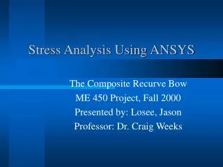
Modeling of Composite Tubes Using ANSYS JEFF KAPKE ME 450 Introduction to CAE May 3, 2000 Submitted to: Professor H.U. Akay
Uses for Composite Materials • Aircraft • Prosthetic Limbs • Auto body • Auto Frame • Bridge Reinforcement • Shafts and Rods • Body Armour
Advantages of Composites • Density of aluminum alloy approximately 2800 kg/m3 • Density of carbon/epoxy approximately 1580 kg/m3 • Tensile strength of aluminum alloy 7075-T6 is 570 MPa • Tensile strength of carbon/epoxy 1830 MPa
Ey E E E E Ex E2 E1 E E Isotropic vs. Orthotropic E = E =E =E =E =E Ex Ey E1 E2
Layers of a Composite Tube X Each color represents a different fiber orientation and change in material properties relative to the Global Axis.
Ex Theta Element Type is SHELL91 Element Coordinate SystemShell 91 From ANSYS Element Library Z Y K L Ex X I J
z y z y x y x z x ANSYS Coordinate System for Shell Element
Deformed and Un-deformedPoint Load with 90o Fiber Orientation
0o Orientation 90o Orientation [0o,90o,45o]s Von Mises Plots of Uniform Loading with Different Orientations
Displacement of Point Loaded 90o/Hoop Orientation (Maximum Displacement 4.934mm)
Displacement Related to Orientation • Uniformly loaded hoop has greatest displacement. • Combination of layers decreases displacement. • Displacement related to stiffness.
Results of Changing Orientation • Hoop or 90o orientation is strong under transverse loading. • Longitudinal or 0o orientation is stiffer in bending. • Combination of orientations increases stiffness and strength.
Difficulties with ANSYS • Creating model is not straight forward and simple. • Meshtool does not recognize that all element axis should coincide within each layer. • ANSYS is too powerful for simple problems.
Advantages of ANSYS • Changing material properties or layer orientation is simple. • Many different orientations can be analyzed in a short amount of time. • ANSYS can predict results before fabricating composite sample. • Complex geometries can be modeled and evaluated easily.
New Ideas • Analyze tube in torsion. • Apply moment instead of load. • Test as a pressure vessel. • Model unique geometries and compare results. • Model a beam or flat plate and compare with actual results.