Download
1 / 13
130 likes | 342 Views
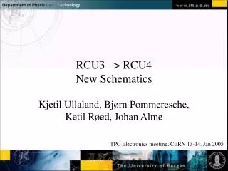
RCU3 –> RCU4 New Schematics. Kjetil Ullaland, Bjørn Pommeresche, Ketil Røed, Johan Alme. TPC Electronics meeting. CERN 13-14. Jan 2005. Motivation for the design revision.

E N D
RCU3 –> RCU4New Schematics Kjetil Ullaland, Bjørn Pommeresche, Ketil Røed, Johan Alme TPC Electronics meeting. CERN 13-14. Jan 2005
Motivation for the design revision • After several beam tests it was found that the Single Event Functional Interrupt-rate was on the limit of what we can tolerate. • Hence, a change in technology was required to provide better protection for upsets. • The Xilinx Virtex architecture provides readback and refresh of the configuration memory without disturbing the firmware.
Most important changes • The Virtex II replaces the Altera APEX as the main FPGA of the RCU • A Flash based CPLD is introduced as a programming support circuit for the Virtex FPGA • A Flash RAM circuit is added in order to make the scrubbing of the configuration memory independent of the DCS-card
Minor changes in the design • The termination network of GTL buffers has been simplified • The number of control lines for the buffers are reduced • An ADC for current measurement is added • The option for 3.3 or 2.5 V as IO voltage is removed (the RCU IO is only 3.3V, the Xilinx core voltage is 1.5 v) • The voltage regulators of the termination network are replaced for better power margin
RCU testcard • A test card (RCU 3.5 ) was designed to speed up testing of the new configuration scheme. • It is populated with a Xilinx Virtex-II, an Altera Max-II CPLD and a Motorola Flash memory. • An optical transceiver is also provided in order to test the RocketIO feature of the Virtex-II5
Configuration Block Diagram DCS board v1.52 JTAG is still used for initial programming and debugging Flash Linux Linux File System Altera FPGA with ARM RCU bus lines RCU4 Altera Max-II Xilinx Virtex-II CPLD Flash memory config file result file mask file SelectMap Bus
Choice of CPLD • The Altera Max II was selected as the configuration support circuit for the Virtex. • However, it turns out it is a "FPGA in disguise". It actually is a RAM-based FPGA with a flash based shadow configuration memory • This means that we have to choose one of the older/standard CPLD circuits from Xilinx, Altera, Lattice or others. • Our latest info from Xilinx in Norway is that all the Xilinx CPLDs use shadow memory. • Problem: We need a relatively large number of Logic Elements/Registers for the scrubbing algorithm. • This has still to be investigated!
Corrections after the September version • Some errors has been found since the September edition of the schematics: • The JTAG chain is routed properly • The clocks are rerouted • The buses are somewhat reconnected to the Xilinx chips, due to the previous routing to some unconnected pins. • The config mode of the Virtex is now set by resistors only • The names of the selectmap-controls signals are changed according to the Virtex labeling • Some resistors are moved and some are changed on these lines • The Hot Swap Enable pin of the Virtex (E21) has a resistor network since we still do not know if this interference with "scrubbing" of the config. RAM. • It is very useful during debugging if the JTAG lines are available as test pads, preferably also so that the chips can be physically detached from each other (if something is really wrong). • 2.5 V analog supply needed if we want to use the Virtex rocket IO feature.