Download
1 / 20
200 likes | 448 Views
Prestressed bolt joints under dynamical load. Kerekes Ervin*, Dr. Szabó Bertalan**, Bernhard Unger* * Steyr-Daimler-Puch AG, Technologie Zentrum Steyr ** Department of Steel Structures, Technical University of Budapest. Contents. Introduction (TZS BME)

E N D
Prestressed bolt joints under dynamical load Kerekes Ervin*, Dr. Szabó Bertalan**, Bernhard Unger* * Steyr-Daimler-Puch AG, Technologie Zentrum Steyr ** Department of Steel Structures, Technical University of Budapest
Contents • Introduction (TZS BME) • Tests (test bench, load spectras, failures) • FE model (whole structure, simplified bolt model, FE loads, stress distributions) • FEMFAT concept (theoretical background) • Fatigue estimation (fatigue load, damage distributions) • Comparison between the tests and the calculations • Conclusions
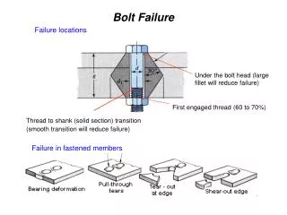
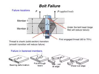
We can find everywhere bolt joints L Notch effect Detachable J
The load spectras and the results of the tests A2 A3 A1/1 and A1/2
The half FE model of the test bench Contact area Contact area
few number of elements linear very fast enough precision Simplified FE model of the bolt joint Advantages:
On the I-beam On the flange plate Load Case 1, Prestress of the bolts (minimal load),
On the I-beam On the flange plate Load Case 2, The total load (maximal load),
FEMFAT technical contents Technological influence factors Load spectra FE stress data (linear stress tensors) FEMFAT Material data Endurance safety factor Damage factor Brake safety factor
FEMFAT calculation concept Load spectra FE model s s ai s mi i N s s mi ai Neuber hypothesis S/N curve s k s D1 ai Relative stress gradient s D N D e s mi S D D2 i s c * k D c * N . D s D . c s * k m i . c * s m Dn
Load case definition for Fatigue Analysis Amplitude stress: Mean stress:
On the I-beam On the flange plate Damage distribution on A1/1 without sequence effect
On the I-beam On the flange plate Damage distribution on A1/2 without sequence effect
In the A1/1 case on the flange plate In the A1/2 case on the flange plate Damage distribution on the A1/1 and the A1/2 cases with sequence effect
In the case of A1/1 In the case of A1/2 The photos of the breaks in the A1/1 and the A1/2 cases Damage Damage !
Comparison the tests and the FEMFAT results Test break FEMFAT calculation without sequence effect FEMFAT calculation with sequence effect
Linear and simplified hypothesis Material properties from literatures Simplified bolt model Lifetime ~ sk ð small amplitude stress changing means high lifetime changing ! Test failures Too few tests Why have we got difference? Calculation side Test side D=1.77 D=1.07 D=0.67
Conclusions • From the tests and fatigue estimation we can say, the dangerous places for this kind of load conditions are the middle screw bores on the flange plate. • The too high prestress is the reason of this weak point • The prestresses on the bolts mean a constant stress, and this is dominant for this type of load.