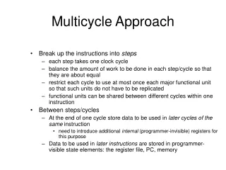
FloorPlan for Multicycle MIPS
Explore the complexity of control unit in multicycle MIPS implementation, defining signals for steps and methods, and examining signal needs. Learn state transitions and more.
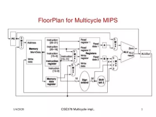

FloorPlan for Multicycle MIPS
E N D
Presentation Transcript
FloorPlan for Multicycle MIPS CSE378 Multicycle impl,.
Control Unit for Multiple Cycle Implementation • Control is more complex than in single cycle since: • Need to define control signals for each step • Need to know which step we are on • Two methods for designing the control unit • Finite state machine and hardwired control (extension of the single cycle implementation) • Microprogramming (read the book about it) CSE378 Multicycle impl,.
What are the control signals needed? • Let’s look at control signals needed at each of 5 steps • Signals needed for • reading/writing memory • reading/writing registers • control the various muxes • control the ALU (recall how it was done for single cycle implementation) CSE378 Multicycle impl,.
Control Signals for Multicycle MIPS CSE378 Multicycle impl,.
Complete Multi-cycle MIPS CSE378 Multicycle impl,.
Instruction fetch • Need to read memory • Choose input address (mux with signal IorD = 0) • Set MemRead signal • Set IRwrite signal (note that there is no write signal for MDR; Why?) • Set sources for ALU • Source 1: mux set to “come from PC” (signal ALUSrcA = 0) • Source 2: mux set to “constant 4” (signal ALUSrcB = 01) • Set ALU controlto “+” (e.g., ALUop = 00 and don’t care for the function bits) CSE378 Multicycle impl,.
Instruction fetch (PC increment) • Set the mux to store in PC as coming from ALU (signal PCsource = 01) • Set PCwrite • Note: this could be wrong if we had a branch but it will be overwritten in that case; see step 3 of branch instructions CSE378 Multicycle impl,.
Instruction decode and read source registers • Read registers in A and B • No need for control signals. This will happen at every cycle. No problem since neither IR (giving names of the registers) nor the registers themselves are modified. When we need A and B as sources for the ALU, e.g., in step 3, the muxes will be set accordingly • Branch target computations. Select inputs for ALU • Source 1: mux set to “come from PC” (signal ALUSrcA = 0) • Source 2: mux set to “come from IR, sign-extended, shifted left 2” (signal ALUSrcB = 11) • Set ALU controlto “+” (ALUop = 00) CSE378 Multicycle impl,.
Concept of “state” • During steps 1 and 2, all instructions do the same thing • At step 3, opcode is directing • What control lines to assert (it will be different for a load, an add, a branch etc.) • What will be done at subsequent steps (e.g., access memory, writing a register, fetching the next instruction) • At each cycle, the control unit is put in a specific state that depends only on the previous state and the opcode • (current state, opcode) (next state) Finite state machine(cf. CSE370, CSE 322) CSE378 Multicycle impl,.
The first two states • Since the data flow and the control signals are the same for all instructions in step 1 (instr. fetch) there is only one state associated with step 1, say state 0 • And since all operations in the next step are also always the same, we will have the transition • (state 0, all) (state 1) CSE378 Multicycle impl,.
Customary notation Instruction decode and read source registers (state 1) Instruction fetch (state 0) Memread ALUSrcA = 0 IorD = 0 Irwrite ALUsrcB = 01 ALUop =00 Pcwrite Pcsource = 00 ALUSrcA = 0 ALUsrcB = 11 ALUop =00 No label because transition is always taken CSE378 Multicycle impl,.
Transitions from State 1 • After the decode, the data flow depends on the type of instructions: • Register-Register : Needs to compute a result and store it • Load/Store: Needs to compute the address, access memory, and in the case of a load write the result register • Branch: test the result of the condition and, if need be, change the PC • Jump: need to change the PC • Immediate: Not shown in the figures. Do it as an exercise CSE378 Multicycle impl,.
State transitions from State 1 State 0 State 1 Opcode = etc Start Opcode “Mem op.” Opcode “R-R.” Opcode “branch.” Opcode “jump.” State 2 CSE378 Multicycle impl,.
State 2: Memory Address Computation • Set sources for ALU • Source 1: mux set to “come from A” (signal ALUSrcA = 1) • Source 2: mux set to “imm. extended” (signal ALUSrcB = 10) • Set ALU controlto “+” (ALUop = 00) • Transition from State 2 • If we have a “load” transition to State 3 • If we have a “store” transition to State 5 CSE378 Multicycle impl,.
State 2: Memory address computation ALUSrcA =1 ALUSrcB = 10 ALUop = 00 State 2 Opcode “load” Opcode “store” State 3 State 5 CSE378 Multicycle impl,.
One more example: State 5 --Store • The control signals are: • Set mux for address as coming from ALUout (IorD = 1) • Set MemWrite • Note that what has to be writtenhas been sitting in B all that time (and was rewritten, unmodified, at every cycle). • Since the instruction is completed, the transition from State 5 is always to State 0 to fetch a new instruction. • (State 5, always) (State 0) CSE378 Multicycle impl,.
Multiple Cycle Implementation • Immediate instructions are not here CSE378 Multicycle impl,.
Hardwired implementation of the control unit • Single cycle implementation: • Input (Opcode) Combinational circuit (PAL) Output signals (data path) • Input (Opcode + function bits) ALU control • Multiple cycle implementation • Need to implement the finite state machine • Input (Opcode + Current State -- stable storage) Combinational circuit (PAL) Output signals (data path + setting next state) • Input (Opcode + function bits + Current State) ALU control CSE378 Multicycle impl,.