Download
1 / 36
390 likes | 423 Views
Design, analyze, and assess the fitness of pressure vessels, heat exchangers, and tanks with the comprehensive software platform EQUIP PASS/EQUIP. Utilizing multiple codes, modules allow for precise strength and stability evaluations, considering various loads and elements. This software streamlines data input, material selection, weight loads, thickness calculations, and more, enhancing the efficiency of your design process. Visualize and customize models, analyze key components, and generate detailed reports effortlessly with EQUIP PASS/EQUIP.

E N D
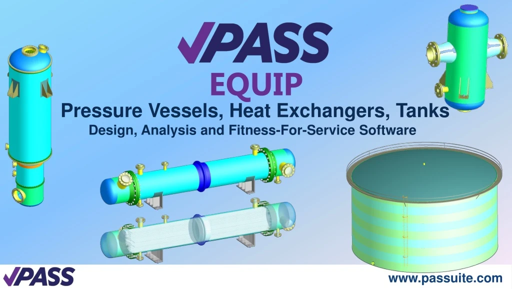
Pressure Vessels, Heat Exchangers, Tanks Design, Analysis and Fitness-For-Service Software EQUIP
PASS/EQUIPFeatures • PASS/EQUIP basic module analyzes strength and stability of horizontal and vertical vessels using ASME, EN, WRC and Russian (GOST, RD) codes • PASS/EQUIP-Columns module analyzes strength and stability of columns considering wind and seismic loads. • PASS/EQUIP-Heat Exchangers module analyzes tube and casing heat exchangers (HE), including analysis of tube plates, tubes, pass partitions, casing, expansion joints, expansion vessel, floating head, and air–cooled heat exchangers. • Calculation of vertical steel tanks, designed for oil and oil product storage, is performed via module PASS/EQUIP-tanks. • PASS/EQUIP- Seismic module analyses strength and stability of horizontal and vertical vessels considering seismic loads.
PASS/EQUIP Basic module • calculation of many elements (shells, heads, transitions, flanges,…) is performed as per ASME sec VII div. 1, EN 13445, WRC and Russian (GOST, RD) codes. • strength calculation of junction point between nozzle and vessel (apparatus) against influence of pressure and external loads, as per as per WRC 537(107)/297 and GOST 34233.3-2017 codes. • selection of elements from Database (shells, heads, flanges (ASME, EN), gaskets, saddle supports, supporting legs, cylindrical and conical supports, nozzles, cross-sections of ribs, reinforcing rings, beam elements of support structure,...); • selection of Materials from the Database (as per ASME, EN, GOST, JB etc.) with possibility of adding new materials. Allowable stress, modulus of elasticity and other values are automatically changed when changing material, temperature or wall thickness; • data input analysis. An error message will be display if all required data are not entered or data are entered incorrectly; • input of additional weight loads, concentrated forces and moments; • thickness calculation (including for external pressure) and calculation of allowable pressure, forces and moments;
PASS/EQUIP Basic module • automatic calculation of values such as weight, length, reinforcing ring properties (in both cylindrical shells and saddle supports), circumference chord length, etc. after input of element dimensions and material properties; • calculation of fluid volume, fill height, filling ratio and hydrostatic pressure in each element of horizontal and vertical vessel; • representation of model structure as a structure tree. • 3D graphic display which allows the colour of separate elements and the entire model to be customized; • "wire-frame" and "transparent" view which allows internal elements to be seen; • when dimensions or load properties of one element are changed, an option to automatically adjust all adjacent elements is given; • automatic creation of precise solid model of vessel and its export to popular solid modelling systems, i.e. ACIS, IGES, Parasolid, STEP. • customization of measurement Units (US, SI, MKS); • analysis of horizontal vessel shells with any number (more than 2) and position of saddle supports; output of diagrams for deformation, bending moments, transverse forces and strength and stability allowances;
PASS/EQUIP Basic module • analysis of bolted caps (with flange joints) as a combined analysis of flange and heads; • calculation of low-cycle fatigue of vessel elements; • strength analysis of shells and heads considering displacement of weld joint edges, angularity and out-of-roundness of the shells; • output, preview and printout of full (with intermediate analysis results) or short reports of element analyses; • output of information on elements that do not meet use or strength requirements; • export and import of vessel models from and to XML files; • export of nozzles to Nozzle FEM format files (*.nzl); • import of vessel models from MechaniCS XML format files.
PASS/EQUIP Columns • determination of lowest vibration frequency period for column type vessels with any number of elements, including support structure; • calculation of forces under wind loads (including resonance vortex excitation) and seismic loads for columns; • strength and stability analysis of column elements; • analysis of “cylinder + cone” support skirt with the option of including a transitional shell; • automatic determination of position and properties of most unsafe cross-section of supporting shell; • calculation of loads on basement and support structure (if any) of columns.
PASS/EQUIP Heat Exchangers • ASME UHX and GOST 34233.7 heat exchanger mechanical design; • input of heat-exchange element properties within a single multi-window interface; • calculation of forces in tube plates, casing and tubes; • analysis of tube plates, casing, tubes, expansion joint, expansion vessel, floating head; • air cooling exchanger
PASS/EQUIP Tanks • tank parameters setting in a single multiwindow dialog; • automatic weight measurement; • strength and stability analysis of the wall, stationary frameless roof and tank head, including wind, snow and seismic loads; • wall anchorage calculation; • calculation of loads on basement; • estimation of allowable stresses on the nozzles of cut-ins in the tank wall.
PASS/EQUIP Seismic • calculation of loads from seismic forces on horizontal and vertical vessels • analysis of vessel elements considering seismic loads; • consideration ofsupport structure and installation height.
PASS/EQUIP References • ASME Boiler and Pressure Vessel Code. Sect.VIII, Div.1. 2013. • ASME Boiler and Pressure Vessel Code. Sect.II. Part D. Materials. 2013. • EN 13445-3. European Standard. Unfired pressure vessels – Part 3. Issue 1 (2002-09). • WRC- 537(107) Welding Research Council. Bulletin. “Local Stresses in Spherical and Cylindrical Shells due to External Loadings”. • GOST34233.1…11-2017. Vessels and apparatuses. Norms and methods of strength calculation. • GOST342283-17. Vessels and Apparatus. Norms and methods of strength calculation • from wind loads, seismic influence and other external loads • STO-SA-03.003-2009. Vessels and apparatuses. Norms and methods of strength calculation. Seismic loads calculation. Standard of Association of Expert organizations of hazardous facilities (Association Rostekhexpertiza) • STO-SA-03-002-2009. Rules for design, fabrication and assembly of vertical cylindrical steel tanks for oils. • …..
PASS/EQUIPCalculating elements Analysis is carried out for each element and includes the following: • cylindrical shells (smooth and with reinforcing rings); • conicaltransitions; • welded heads, bolted heads and caps (spherical, ellipsoidal, torispherical, conical and flat (including reinforcing ribs); • flange joints; • nozzles into shells and heads; • saddle supports and cylindrical shells for horizontal vessels; • cylindrical shells and heads in areas of intersection with supporting lugs and legs for vertical vessels; • cylindrical shells, conical elements and dished heads at attachment points of lifting lugs, ears and trunnions; • elbows; • column elements under wind and seismic loads, including those mounted on a support structure; • supportshells of columns ; • tube plates, casing, tubes, expansion joint, expansion vessel, floating head of heat exchange vessels;
PASS/EQUIP Material Database • Selected from database (ASME II Part D, EN, GOST 34233.1, PNAE G-7-002-86, GOST R 54522-2011 etc.) • set by user’s Material
PASS/EQUIP2nd step – Creating model elements Analysis is carried out for each element and includes the following: • cylindrical shells (smooth and with reinforcing rings); • conicaltransitions; • welded heads, bolted heads and caps (spherical, ellipsoidal, torispherical, conical and flat (including reinforcing ribs); • flange joints; • nozzles into shells and heads; • saddle supports and cylindrical shells for horizontal vessels; • cylindrical shells and heads in areas of intersection with supporting lugs and legs for vertical vessels; • cylindrical shells, conical elements and dished heads at attachment points of lifting lugs; • bends; • column elements under wind and seismic loads, including those mounted on a support structure; • supportshells of columns ; • tube plates, casing, tubes, expansion joint, expansion vessel, floating head of heat exchange vessels
PASS/EQUIPExport 3D model to AutoCadand otherpopular CAD-system and finite element analysis software via formats IGES, STEP, ACIS, ParaSolid
PASS/EQUIP Vertical Column Vessel Estimation of natural period by Rayleigh method
PASS/EQUIP Heat exchanger Automatic determination of tube sheet design parameters
PASS/EQUIP Tank Area of allowable nozzle loads
Design bureaus and departments of the plants and research institutes executives in the industry (more than 350 companies) Oil refining Chemical Petrochemical Oil and Gas thermal power … others PASS/EQUIPUsers • Russia • OJSC "VNIPIneft“ • OJSC "VNIIneftemash" • JSC "NIICHIMMASH" • LLC “Lengiproneftechim” • JSC «IrkutskNIIhimmash» • JSC "Samaraneftekhimproekt“ • ThyssenKrupp Industrial Solutions • JSC “Bashkir soda company” • JSC "GazpromneftekhimSalavat“ • JSC "Onpz.gazprom-neft“ • PJS company Kazanorgsintez • OJSC "Lukoil -Nizhegorodnefteorgsintez" • JSC "VSMPO-AVISMA“ • PJSC "Nizhnekamskneftekhim“ • CJSC "Ryazan oil processing company “ • OJSC "Sayanskkhimplast“ • JSC "Volgogradneftemash" • JSC "Siberian group of chemical enterprises“ • OJSC "Sibneftemash“ • JSC "Zenit-himmash“ • JSC «Uzbekchimmash Plant» (Uzbekistan • Pavlodar Oil Chemistry Refinery (Kazahstan) • OJSC “Naftan” (Republic of Belarus) • JSC “MOZYR OR” (Republic of Belarus) • … • Hitachi Zosen Corp (Japan) • BURGASNEFTEPROJECT (Bulgaria) • InitecPlantasIndustriales (Spain) • IDESA (Spain) • TUV Thuringen (Germany) • GBM S.r.l. (Italy) • SKODA JS (Czech Republic) • CNPC EAST OF CHINA DESIGN & RESEARCH INSTITUTE(China) • Other
PASS/EQUIP NOZZLE-FEM Strength and stiffness calculation of junctions between nozzles and vessel (apparatus) shells and heads, as well as laterals in piping and junctions between nozzles and shells of steel tanks for oil storage software
NOZZLE-FEMmain function Defines the membrane, bending, and total stresses in the joints of the fittings (including downhill) with the sides and bottoms of vessels (apparatuses), and locations of tie-ins to pipelines from the action of external loads and pressure; Defines allowable membrane and a commonstresses; calculation of reinforcement openings from internal pressure; gives conclusion the efficiency of the units; determines the stiffness (compliance) of the node of the tie; calculation of strength and stiffness for WRC 537/107(297).
NOZZLE-FEM Deflected mode Differentiation between general, local and peak stresses
NOZZLE-FEM The finite element model meshing The influence of the size of the finite element (A finite element model of the junction, corresponding to the 1st (a) and 5th (b) the level of meshing)
NOZZLE-FEM Levels of FEM meshing, deflected mode The influence of the size of the finite element
Calculation of vessel by ASME VIII Div.2 Code; The introduction of a new mesh generator that allows you to cover more general configuration structures (saddle supports, the supporting legs (stand), the simultaneous interaction of several nozzles; Full integration "PASS/EQUIP" with “Nozzle-FEM"; Integration "Nozzle-FEM" with program "START“ software on the automatic determination of the stiffness of the insert fittings, and the coefficients of the intensification of stresses in the tees; Calculation of the strength and stability of the frame tank roof using FEM; Supplement of the database of materials and elements; Client’s wishes "PASS/EQUIP", “Nozzle-FEM" development plan for 2018-2020 period supplement
www.passuite.com sales@passuite.com