Download
1 / 64
640 likes | 725 Views
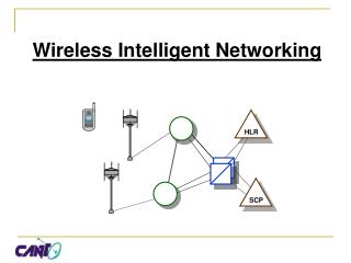
Wireless Networking Primer (few topics that may help in understanding other lectures). Nitin Vaidya University of Illinois at Urbana-Champaign. What Makes Wireless Interesting?. Absence of wires facilitate mobility Signal attenuation Spatial reuse Diversity Multi-user diversity

E N D
Wireless Networking Primer(few topics thatmay help in understanding other lectures) Nitin Vaidya University of Illinois at Urbana-Champaign
What Makes Wireless Interesting? • Absence of wires facilitate mobility • Signal attenuation • Spatial reuse • Diversity • Multi-user diversity • Antenna diversity • Time diversity • Frequency diversity • Wireless devices often battery-powered • Broadcast medium makes it easier to snoop on, or tamper with, wireless transmissions
Transmission “Range” Whether a transmission is received reliably or not depends on • Transmit power level • Channel conditions (time-varying) • Interference (time-varying) • Noise (not deterministic) • Packet size • Modulation scheme (bit rate) • Error control coding • Transmission rate • Transmission not received by all “neighbors” reliably • Not all nodes can “hear” each other • Time-varying outcome of transmissions
Medium Access Protocol (MAC) Wireless channel is a shared medium, requiring suitable MAC protocol. Performance of the MAC protocol depends on • Channel properties • Physical capabilities • Single interface? • One packet at a time? • One channel at a time? • Antenna diversity? Assume single interface, single channel, single antenna, one packet at a time, small propagation delay
“Basic” Protocol • Simple rule (a distributed protocol): Transmit packet immediately (if not transmitting already) Shortcomings • No provision for reliability • No detection of “collisions”
Reliability: A Retransmission Protocol • Stop-and-wait
A Mechanism to Reduce Collision Cost Packet loss may occur due to collisions. To reduce cost: • “Reserve” the wireless channel before transmitting data • Send short control packets for reservation • Collision may occur for control packets, but they are short lower collision cost • Once channel reserved, data transmission (hopefully) reliable
RTS-CTS Exchange • Node A sends RTS to B Duration of proposed transmission specified in RTS • B responds with CTS • Host A sends data • Other hosts overhearing RTS keep quiet for duration of proposed transmission • Works alright if all nodes within “range” of each other
RTS-CTS • RTS-CTS reduce collision cost • If data packets too small, sending RTS-CTS not beneficial A possible implementation: Send RTS-CTS only for data packets withsize > RTS-threshold
Carrier Sense Multiple Access (CSMA)(to reduce collisions) • Listen-before-you-talk • A host may transmit only if the channel issensed as idle
Carrier Sensing (Approximation) Implementation using Carrier Sense (CS) threshold Pcs • If received signal power<CS threshold Channel idle • Else channel busy In reality, efficacy of carrier sensing affected by noise & interference.
D B C A power distance Carrier Sense Multiple Access (CSMA) • D perceives idle channel although A is transmitting D’s CS Threshold
power distance Carrier Sense Multiple Access (CSMA) • D perceives busy channel when A transmits D B C A D’s CS Threshold
Trade-Off • Large carrier sense threshold More transmitters Greater spatial reuse & more interference • Trade-off between spatial reuse and interference
D B C A Impact of CS Threshold on Interference • Suppose C transmits even though A is already transmitting Path gain g = received power / transmit power
Hidden & Exposed Terminals • Collisions may occur despite carrier sensing • Smaller carrier sensing threshold can help • But increases the incidence of exposed terminals ?
Hidden & Exposed Terminals • Cannot eliminate all collisions using carrier sensing • Trade-off between hidden and exposed terminals • Optimal carrier sense threshold function of network “topology” and traffic characteristics
Collision Detection • Ethernet uses carrier sensing & collision detection (CSMA/CD) • Transmitter also listens to the channel • Mismatch between transmitted & received signal indicates mismatch • Stop transmitting immediately once collision is detected Reduces time lost on a collision
Collision Detection in Wireless Networks • Receiving while transmitting: Received signal dominated by transmitted signal • Collision occurs at receiver, not the transmitter Collision detection difficult at the transmitterwithout feedback from the receiver
Solutions for Hidden Terminals • Busy-tone • Virtual carrier sensing • Carrier sensing mechanism discussed earlier will be referred to as physical carrier sensing, to differentiate with virtual carrier sensing
Virtual Carrier Sensing • RTS specifies duration of transmission • CTS also includes the duration • Any host hearing RTS or CTS stay silent as shown RTS CTS
Virtual Carrier Sensing • Host C may not receive RTS and still cause collision at host B • SINR = Signal-to-interference-and-noise ratio = S / (I + N) • Assume “SINR-threshold model” assume that SINR necessary/sufficient for reliable delivery (approximation of reality)
SINR for RTS reception at C is upper bounded as • If C transmits while A is receiving an Ack from B, SINR for Ack reception at A is upper bounded as RTS CTS
Virtual Carrier Sensing • C’s silent interval below is not adequate to ensure reliable Ack reception at A • Similarly, D’s silent interval not adequate to ensure reliable data reception at B RTS CTS
Virtual Carrier Sensing - Modification • Greater protection from interference • Reduce book-keeping with multiple nearby transmitters
“Space Reserved” by Virtual CS RTS RTS Reminder: “Range” not necessarily circular in practice
Physical & Virtual CS • Physical carrier sensing (PCS) &virtual carrier sensing (VCS)may be used simultaneously • Channel assumed idle only if both PCS and VCS indicate that the channel is idle
Backoff Intervals • Channel sensing not enough to prevent multiple nodes to start transmitting “at nearly the same time” • Reduce such collisions by controlling access probability • Implementation using backoff intervals: • Choose backoff interval uniformly in range [0, cw-1] • Initialize a counter by this value • Decrement counter after each slot if channel detected idle • Transmit when counter reaches 0
Responding to Packet Loss • To reduce collisions due to excessive load on the channel, access probability should be reduced • May be achieved by increasing the window over which backoff interval is chosen • Exponential backoff : [0,c-1] [0,2c-1]
IEEE 802.11Distributed Coordination Function (DCF) • Physical & virtual carrier sensing (RTS-CTS) • Contention window (cw) : Backoff chosen uniformly in [0,cw] • Exponential backoff after a packet loss • Contention window reset to CWmin on a success
Hybrid Networks Ad Hoc Networks
Routing Protocols forMobile Ad Hoc Networks (MANET) • Proactive protocols • Determine routes independent of traffic pattern • Traditional link-state and distance-vector routing protocols are proactive (and could be extended for MANET) • Reactive protocols • Maintain routes only if needed • Hybrid protocols Similar solutions may be used in “mesh” networks
Example of Reactive Routing:Dynamic Source Routing (DSR) [Johnson96] • When node S wants to send a packet to node D, but does not know a route to D, node S initiates a route discovery • Source node S floods Route Request (RREQ) • Each node appends own identifier when forwarding RREQ
Route Discovery in DSR Y Z S E F B C M L J A G H D K I N Represents a node that has received RREQ for D from S
Route Discovery in DSR Y Broadcast transmission Z [S] S E F B C M L J A G H D K I N Represents transmission of RREQ [X,Y] Represents list of identifiers appended to RREQ
Route Discovery in DSR Y Z S [S,E] E F B C M L J A G [S,C] H D K I N • Node H receives packet RREQ from two neighbors: potential for collision
Route Discovery in DSR Y Z S E F [S,E,F] B C M L J A G H D K [S,C,G] I N • Node C receives RREQ from G and H, but does not forward it again, because node C has already forwarded RREQ once
Route Discovery in DSR Y Z S E F [S,E,F,J] B C M L J A G H D K I N [S,C,G,K] • Nodes J and K both broadcast RREQ to node D • Since nodes J and K are hidden from each other, their transmissions may collide
Route Discovery in DSR Y Z S E [S,E,F,J,M] F B C M L J A G H D K I N • Node D does not forward RREQ, because node D is the intended target of the route discovery
Route Discovery in DSR • Destination D on receiving the first RREQ, sends a Route Reply (RREP) • RREP is sent on a route obtained by reversing the route appended to received RREQ • RREP includes the route from S to D on which RREQ was received by node D
Route Reply in DSR Y Z S RREP [S,E,F,J,D] E F B C M L J A G H D K I N Represents RREP control message
Dynamic Source Routing (DSR) • Node S on receiving RREP, caches the route included in the RREP • When node S sends a data packet to D, the entire route is included in the packet header • hence the name source routing • Intermediate nodes use the source route included in a packet to determine to whom a packet should be forwarded
Data Delivery in DSR Y Z DATA [S,E,F,J,D] S E F B C M L J A G H D K I N Packet header size grows with route length
DSR Optimization: Route Caching • Each node caches a new route it learns by any means • When node S finds route [S,E,F,J,D] to node D, node S also learns route [S,E,F] to node F • When node K receives Route Request [S,C,G] destined for node, node K learns route [K,G,C,S] to node S • When node F forwards Route Reply RREP[S,E,F,J,D], node F learns route [F,J,D] to node D • When node E forwards Data [S,E,F,J,D] it learns route [E,F,J,D] to node D • A node may also learn a route when it overhears Data packets
Use of Route Caching • When node S learns that a route to node D is broken, it uses another route from its local cache, if such a route to D exists in its cache. Otherwise, node S initiates route discovery by sending a route request • Node X on receiving a Route Request for some node D can send a Route Reply if node X knows a route to node D • Use of route cache • can speed up route discovery • can reduce propagation of route requests
Use of Route Caching [S,E,F,J,D] [E,F,J,D] S E [F,J,D],[F,E,S] F B [J,F,E,S] C M L J A G [C,S] H D K [G,C,S] I N Z [P,Q,R] Represents cached route at a node (DSR maintains the cached routes in a tree format)
Use of Route Caching:Can Speed up Route Discovery [S,E,F,J,D] [E,F,J,D] S E [F,J,D],[F,E,S] F B [J,F,E,S] C M L [G,C,S] J A G [C,S] H D K [K,G,C,S] I N RREP RREQ Z When node Z sends a route request for node C, node K sends back a route reply [Z,K,G,C] to node Z using a locally cached route