Download
1 / 27
280 likes | 445 Views
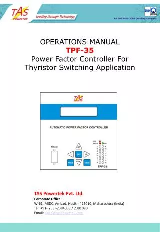
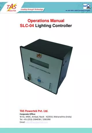
Operations Manual SLC-04 Lighting Controller. TAS Powertek Pvt. Ltd. Corporate Office: W-61, MIDC, Ambad, Nasik - 422010, Maharashtra (India) Tel: +91-(253)-2384038 / 2381090 Email: sales@taspowertek.com. NOTE

E N D
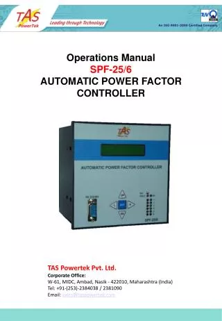
Operations Manual SLC-04 Lighting Controller TAS Powertek Pvt. Ltd.Corporate Office: W-61, MIDC, Ambad, Nasik - 422010, Maharashtra (India)Tel: +91-(253)-2384038 / 2381090Email: sales@taspowertek.com
NOTE These instructions do not purport to cover all details or variations in equipment, nor to provide for every possible contingency to be met in connection with installation, operation or maintenance. Should further information be desired or should particular problems arise which are not covered sufficiently for the purchasers purposes, the matter should be referred to our TAS Powertek Pvt. Ltd., office. The contents of this instruction Manual shall not become part of or modify any prior or existing agreement or relationship. The sales contract contains the entire obligations of TAS Powertek Pvt. Ltd. The warranty contained in the contract between the parties is the sole warranty of TAS Powertek Pvt. Ltd. Any statements contained herein do not create new warranties or modify the existing warranty. The reproduction, transmission or use of this document or its contents is not permitted without express written authority. Offenders will be liable for damages. All rights are reserved.
Index Index Page ------------------ 1 Features & Specifications ----------- 2 Mechanical Dimensions ------------------- 3 Functional Block diagram ------------------ 4 Back Side terminal layout ------------------ 5 Voltage control Energy saving ESM-1 ------ 6 Phase cutting control Energy save ESM-2 & 3 7 Power and Control Wiring Diagram -------- 8 Front Face of SLC-04 ----------------------- 9 Serial Communication Hardware details --- 10 Various Display Parameters ---------------- 11 Parameter Editing Methods ----------------- 14 Parameter Editing Sub-menu Level-1 ---- 15 Parameter Editing Sub-menu Level-2 ---- 17 Fault finding Guidelines --------------------- 20 Energy Saving Calculations ----------------- 22 GSM- Enabled SCADA connectivity --------- 23 - 1 -
Features: • Totally Micro-processor controlled Digital Signal processing • logic for measurements. • All measurements with 1.0 class accuracy. • Supports various energy saving functions. • Various modes for energy saving like Voltage Control and Phase • cutting control. • Load V,Iph, In and Cap. current THD measurement. • Totally 6 outputs control for various controls. • Additional load switch on sensing puts lamps to full intensity and after • stipulated time delay brings it back to voltage reduced saving. • Flicker free changeover for fluorescent lamps with voltage control • operation. • Standard 144 X 144 cabinet for panel door flush mounting. • Serial communication through standard TAS as well as MODBUS • protocols. • Protections / Annunciation provided (user settable): • Over/under Voltage • Over/Under frequency (internally set limits) • Over load. • Load unbalance. • RTC battery down. • Data logging for various parameters for 2months period at an • interval of 1hr. • Unit comes along with PC (Windows compatible) software • for downloading and viewing the logged data. • GSM modem connectivity drivers are in built and can be connected with • SMS driven SCADA system. • Power factor correction logic (optional feature). • Specifications: • Feed-back Voltage:440Volt (+10%/-30%) • Current input : 1Amp for load feed-back. Optional 5Amp. • Measurement Accuracy: Class 1.0 • Auxiliary Supply: 525Vac to 300Vac. • Voltage changeover time for contactors from –99mS. to +99mS. • Output commands: • NO contacts each with current rating of 0.5Amp AC. at • 240Vac. • RS-232 baud rate selectable from 4.8kBPS to 38.4kBPS. • Operating temperature: 0 to 55oC. • 1.0class measurement Operating temperature: 0 to 50oC. • Storage temperature: -10 to +75oC. • Humidity: 0 to 98%. • Supply frequency: 45Hz to 55Hz. - 2 -
135 135 144 120 144 6 Mechanical Dimensions: Recommended size for cutout on panel door is 138 X 138. All Dimensions given are in mm. Maximum weight: (with clamps and terminals) = 2.5kg. - 3 -
3 channel Current f.b. 3 channel Voltage f.b. EEPROM For Data Logging Functional Block Diagram: SLC-04 V, I, PF and Power Measurement Block (Load Manager) RS-232 Serial Communication. TAS-01 & GSM Modem driver Protocol stack. Keyboard, Display and Other support Functions Block. • Calculation • Block for • Energy Parameters • Harmonic analysis Real Time Clock (RTC) Block for outputs On/Off Outputs Commands for energy saving control. Power Supply Block. Above block diagram gives the functional blocks that are built into SLC-04 Street Lighting controller. These blocks are made up with the combination of functions from hardware and corresponding firmware that resides in the Program memory of the micro-processor used therein. Even though the basic blocks exists as shown in the diagram, there functionality is interdependent. The entire combination is carefully designed so as to have minimum effects of Electrical and Electromagnetic noise level on the functionality of this SLC-04. The firmware written takes into account the various error handling eventualities so that the functioning of this PF relay is error free and highly reliable. - 4 -
Voltage Feedback Terminals. Auxiliary Supply Terminals. Current Feedback terminals RS-232 back side terminals Output command terminals Back Side Terminal Layout: - 5 -
3ph Mains N C1 SLC-04 Controller. C3 C2 L O A D Energy saving with Voltage control through switchgear. (ESM-1) In the scheme shown in the above diagram, a usage of duel output tapping transformer is necessary. Contactor C1 shown in this scheme is optional and is used for controlling the input supply to the transformer. C2 contactor is normally used for voltage boosting and C3 contactor is normally used for voltage lowering. Voltage boosting is during the supply under-voltage conditions as well as during initial switch On. The fluorescent lamps normally requires full voltage for turn On and that too till it achieves its full luminous intensity. Once lamps are fully lighted up, the voltage can be brought down. This reduces the output luminous intensity of the fluorescent lamps but does not put Off the lamps. But by doing so, it reduces the energy input to the lamps. SLC-04 is programmed so that it can switch On and Off the lamp load at pre-programmed time automatically as well as it can control the time wise energy saving operation too. - 6 -
C1 C4 Ph-1 R-Phase Load Ph-2 C5 Y-Phase Load C6 Ph-3 B-Phase Load Neutral Energy saving with Phase control through switchgear. (ESM-2 & 3) In the scheme shown in the above diagram, a usage of single contact switchgear is necessary. Contactor C1 shown in this scheme is optional and is used for controlling the input supply to the system. P1, P2 and P3 switchgears that are primarily single contact switchgear are for giving the supply to individual phase loads. Normally, in such schemes, every third lamp on the street is distributed between the three phases. Thus if only Ph-1 is on, then every one lamp in three lamps would be in on condition. Similarly, if any two phases are on then every two lamps out of three would be on. During less requirement hours, the scheme can save upto 66% energy.* SLC-04 is programmed so that it can switch On and Off the lamp load at pre-programmed time automatically as well as it can control the time wise energy saving with either two phase or single phase control too. SLC-04 is intelligent enough to keep track of the equal load utilisation, keeping the maintenance requirements at lowest level. *conditions apply. - 7 -
O/p1 O/p2 O/p3 O/p4 O/p5 O/p6 COM Voltage & Phase control scheme combined: Three phase Power & Control wiring diagram. C1 C3 C2 Ph-1 C4 R-Phase Load C5 Ph-2 Y-Phase Load C6 Ph-3 B-Phase Load N L1 L2 Auxiliary Supply + - + - + - Bph Yph Rph Load Current Feedback V N - B-Ph F Y-Ph B R-Ph RS-232 TX RX G SLC-04 GSM MODEM - 8 -
Front Facia of SLC-04: LCD Display Step status LED indication Serial Communication Port Membrane Keypad Usage of the UP and DN key makes the LCD display to scroll up and down. This is used for display of various status as well as for viewing the On line measured electrical values. These keys are also used for changing values in Parameters Editing mode . Usage of ENT key is for entering the submenu and / or for setting up some values. The L and R keys are used in changing the position of the cursor from Left to Right and vice-versa. - 9 -
5 4 3 2 1 6 7 8 9 RXD GND TXD RS-232 serial communication 9 pin D connector: RS-232 cable connection Details: - 10 -
10:10 07/11/06 SUN E1VE2E3 OK Display of Various Parameters / Status: This is default display screen giving information on Time, Date, Modes of operation and health status. The LCD display is made up of 16 ASCII characters per line and there are 2 lines to this display. In this default display, first line indicates the time HH:MM and the date dd/mm/yy. Second line shows the modes of operation and the health status. Second line first word is three characters in length. It is : FIX or SUN: This states SLC-04 working mode for Overall On / Off timing. These timings can be fixed “FIX” as stated by user or can be Sunset/Sunrise “SUN” timing. The table of sunset and sunrise timings for all 365 days a year for a given location resides in the memory of SLC-04. This table can be edited and then programmed in SLC-04 by user through PC serial interface. Windows based program for the said purpose is normally supplied on CD-ROM which comes along with this controller. Second line next seven characters gives various modes. These are “E1”, “V”, “E2”, “E3”. E1: This is ESM1 (Energy Saving Mode 1). In this the scheme is used with voltage control. This display comes on when there is a changeover from C2 contactor to C3 contactor. I.e. the reduced voltage is applied to the lamps. V: This is a voltage control mode. This is active only if ESM1 is activated. With C3 contactor on, if an under-voltage is observed at any one of the phases of input supply voltage, it changes over from C3 to C2 and this “V” is displayed on the screen. This is to prevent the fluorescent lamps being turned off due to excessive under-voltage applied to it. E2 & E3: These are ESM2 and ESM3 energy saving modes. Both these modes are used with phase cutting energy saving. ESM2 is with one phase cutting and ESM3 is with two phase cutting. For ESM3 to be enabled, ESM2 is mandatory to be enabled. Whenever these modes are active, the display E2 and/or E3are turned on. Second line last part is word with two ASCII characters. These are either “OK” or “BF” or “NV” or “UV”. OK or BF or NV or UV: The last part of the display that is blinking every 500mS indicates the working status of SLC-04. “OK” indicates that unit is working fine without any trip conditions. If there is other indication, the meaning of the same can be as: OK : No Fault BF : Internal Battery Failure. NV : Internal NV RAM check-sum fault. UV : Under voltage on mains beyond working limit. - 11 -
Indicates Average Voltage value of three phase with respect to Neutral. Indicates the average Current value in three phases of the input supply of the panel. Here kW is the active power drawn and SkW is the savings in kW. This SkW is seen in ESM conditions. Indicates Apparent Power in terms of kVA value. Active Energy (kWh) counter. Saved Active Energy (kWh) counter. Apparent Energy (kVAh) counter. Overall Power Factor of the input supply to panel. Mains Supply frequency. Ph-1 (R-phase) Voltage. Ph-N value. Ph-2 (Y-phase) Voltage. Ph-N value. Ph-3 (B-phase) Voltage. Ph-N value. Ph-1 (R-phase) Current value. Ph-2 (Y-phase) Current value. Ph-3 (B-phase) Current value. Neutral Current value. - 12 -
Display of Various Parameters. Ph-1 (R-phase) Power Factor value. Ph-2 (Y-phase) Power Factor value. Ph-3 (B-phase) Power Factor value. Ph-1 (R-phase) Active Power (kW) value. Ph-2 (Y-phase) Active Power (kW) value. Ph-3 (B-phase) Active Power (kW) value. Ph-1 (R-phase) Reactive Power (kVAr) value. Ph-2 (Y-phase) Reactive Power (kVAr) value. Ph-3 (B-phase) Reactive Power (kVAr) value. Ph-1 (R-phase) Apparent Power (kVA) value. Ph-2 (Y-phase) Apparent Power (kVA) value. Ph-3 (B-phase) Apparent Power (kVA) value. - 13 -
PRESS Enter Pwd: **** PRESS PRESS Method for Keyboard/Display usage. Flow chart for entering into different modes: If Password Option is Enable/Disable. Enable Disable Default Display mode Enter the 4 Digit password By use of L, R, UP & DN Keys. IF PASSWORD Correct? 1 2 3 4 5 6 7 8 9 10 11 12 13 14 15 16 NO YES * - 14 -
* 1.General 2.System 3.Schedule Cont. 4.Schedule Para. 5.Communication Parameter Editing Sub-Menu LEVEL 2 Sub-menu Level 1 for Parameter Editing. Parameter Editing Submenu Level 1: 1.General: Parameters related with general function and Input/Output 2. System: Electrical system (Mains supply) related parameters. 3. Schedule Control: Schedule Control setting. Various timings etc. 4. Schedule Parameter: Overall Schedule parameter settings. 5. Communication: Parameters related with communication and data logging. - 15 -
Sub-Menu Level 1. Sub-Menu Level 1. PRESS PRESS PRESS PRESS PRESS PRESS PRESS PRESS PRESS PRESS PRESS PRESS PRESS PRESS PRESS PRESS Cursor Blinking at Parameter Values. Cursor Blinking at Parameter Values. 1.Submenu L2: **** 1.Submenu L2: **** 1.Submenu L2: **** 1.Submenu L2: **** key to increment value. Key to decrement value. Key to shift cursor Left. Key to shift cursor Right. key to increment value. Key to decrement value. Key to shift cursor Left. Key to shift cursor Right. 2.Submenu L2: **** 2.Submenu L2: **** 2.Submenu L2: **** 2.Submenu L2: **** key to increment value. Key to decrement value. Key to shift cursor Left. Key to shift cursor Right. key to increment value. Key to decrement value. Key to shift cursor Left. Key to shift cursor Right. 3.Submenu L2: **** 3.Submenu L2: **** Exit: No Save Exit: No Save Exit: No Save Exit: No Save Without saving Default Display. Default Display. With saving Screen for 1second Saving In EEProm Saving In EEProm Exit: With Save Exit: With Save Parameter Editing Method: (For Submenu Level 2 : L2) - 16 -
Parameter Editing Submenu Level 2: Edit Parameters - General Edit Parameters - System Edit Parameters - Schedule Control - 17 -
Parameter Editing Submenu Level 2: Continued: Edit Parameters - Schedule Control Edit Parameters -Schedule Parameter - 18 -
Parameter Editing Submenu Level 2: Continued: Edit Parameters - Communication Note that all the parameters in the Sub-Menu Level 2 should be carefully filled in the SLC-04. Failing to put the correct parameters can make SLC-04 to malfunction. Its therefore advised that a trained person should only be allowed to change these values. - 19 -
Fault Finding Guidelines : - 20 -
A Voltage 240V 220V 200V Lamp Knee Voltage 100V B 300W 380W 500W Wattage Voltage 240V 220V 200V 20KHz. 100V 50Hz. 300W 380W 500W Cut off level Wattage Energy Saving Calculation: Typical Characteristics. 1kW / 240V Mercury lamp characteristics. The above characteristics even though typical, matches with a minor differences with most of the fluorescent lamp manufacturers. In view of the same, SLC-04 calculates the energy saving on the basis of typical graph as shown hereunder. - 22 -
SLC-04 Controller. (RTU) GSM-SMS Master Control Unit. Server. MCU. Communication On GSM-SMS GSM Modem Voltage and/or Phase Control Switchgear / Servo Block. L O A D 1 L O A D 2 L O A D 3 General Scheme with SCADA: • The communication between the RTU and MCU necessitates the following requirement: • Per MCU about 2000 units should be able to communicate. • Every RTU should be able to transmit the data at every one hour. • Every RTU should be able to send the event triggered communication. This is for indicating the faults and Power ups and Power downs. • The data size to be sent can be fitted within 100 ASCII characters. • The reliability of communication should be good, but occasional data loss (say one in 200 or 300) would not make a great problem too. • The communication charges should be as low as possible. • The above diagram shows the RTU and MCU communication link. - 23 -
SLC-04 SLC-04 SLC-04 Overall Scheme with SCADA: The overall scheme with the multiple number of SLC-04 (as RTU – Remote Terminal Units) communicating with MCU on GSM based SMS mode of communication. - 24 -
Our Contact Details: Corporate Office/Works/Design Centre: W-61, MIDC, Ambad, Nasik - 422010, Maharashtra (India)Tel: +91-(253)-2384038 / 2381090Email: tas@taspowertek.com Marketing and After-Sales Service:A/58, Kamal Pushpa, K.C. Road, Bandra, Mumbai-400050.Tel: +91-9930513923Email: sales@taspowertek.com Regional Office: Delhi191-B, Ground Floor, Padam Nagar (Filter Market),New Delhi - 110007 (India).Tel: +91-9911615701Email: delhi@taspowertek.com - 25 -