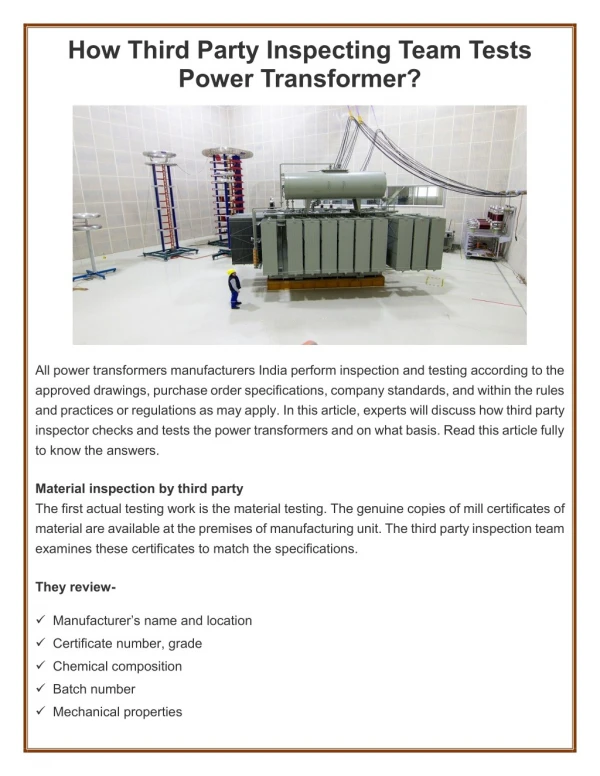
Download
1 / 50
500 likes | 520 Views
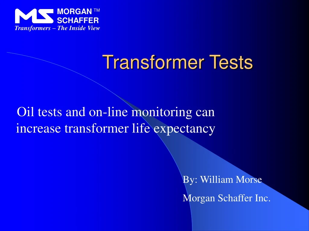
MORGAN. TM. SCHAFFER. Transformers – The Inside View. Transformer Tests. Oil tests and on-line monitoring can increase transformer life expectancy. By: William Morse Morgan Schaffer Inc. Transformers. The heart of a substation Needed to transmit electricity over long distances

E N D
MORGAN TM SCHAFFER Transformers – The Inside View Transformer Tests Oil tests and on-line monitoring can increase transformer life expectancy By: William Morse Morgan Schaffer Inc.
Transformers • The heart of a substation • Needed to transmit electricity over long distances • Steps up or steps down voltage
The Inside View Ready to work again Ready for repair
Oil, the Blood of the Transformer • Part of the Insulation System • Excellent dielectric properties • Cools the transformer • Excellent heat transfer properties • Ease of access
Description ASTM Number Dielectric Strength D-877/D-1816 Acidity D-974 Interfacial tension D-971 Color D-1500 Water Content D-1533 Density D-1298 Visual examination D-1524 Power factor D-924 Dissolved gas analysis D-3612 Inhibitor content D-4768 Furan Analysis D-5837 Metals Analysis ICP Standard ASTM Tests for Insulating Oil
Dielectric Strength Acceptable limit for serviced aged oil: 25 kV
Interfacial Tension Acceptable limit for serviced aged oil: 18 dynes/cm
Water Content The Past And The Present Limit for serviced aged oil: 35 ppm
Dissolved Gas Analysis The most important test you can perform on your transformer
Dissolved Gas Analysis • High vacuum gas extraction apparatus • Extracts all dissolved gases found in the oil sample • Determines dissolved water in ppm as well • Extraction of all gases in less than 2 minutes
Gas Chromatographic Analysis CO2 C2H4 CO CH4 C2H6 C2H2
Two More Important Tests • Furan analysis • Determines the state of the solid insulation • Metals analysis • Used to pin point the location of a fault
Predictive Maintenance • On-site analyzers • Increase the frequency of testing • More data points – Better decisions • On-line monitors • Needed for critical transformers • Warn of developing problems between routine maintenance
PHA-1000 Hydrogen Analyzer Fastest way of screening transformers. Analyzes Hydrogen - A key gas produced by all fault types High sensitivity and wide range Simple operation
Accurate H2 readings in 60 seconds Analysis of H2 only = No cross contamination No special training required
MYRKOS Fault Gas Analyzer A Full DGA Lab in the field
Typical Gas Extraction Apparatus • High vacuum gas extraction apparatus • Fragile • Not very portable • Special training required
The Shake Test Syringe Completely portable No special training required Syringe must be filled so that metering pin is completely outside of syringe cap.
An exact amount of oil is measured using a metering pin located on the syringe piston shaft. Eject the excess oil by pushing the piston until the metering pin hits the syringe cap.
Mixing the oil with CO2 free ambient air: Ambient CO2 free air is pulled into the syringe which is then vigorously shaken to speed up gas diffusion from the liquid phase to the gas phase. • Connect syringe to CO2 trap • Open syringe and CO2 trap • Slowly pull syringe piston to the end • Close syringe and CO2 trap • Disconnect CO2 trap
Method accepted by IEC 60567 and ASTM D-3612 Complete DGA in 2 minutes on-site
Once the test is initiated, automatic sampling occurs and outputs are obtained from both modules (A & B) simultaneously. Calibration is then performed at a click of the mouse button.
On-line Monitors • Continuously measure gas concentration • Store data and trigger alarms
CalistoDissolved Hydrogen and Water Monitor Intelligent Electronic Device IED Highly Accurate and Precise Monitors Oil-Filled Transformers Designed for Extreme Environments Communicates with the World
H2 detection cell Specially designed thermal conductivity detector Specific to Hydrogen No interference from other gases
H2 detector port Gas extraction chamber Oil circulation pump Water sensor Primary Heat exchanger
CalistoDissolved Hydrogen and Water Monitor Continuous Hydrogen measurement Two alarm levels Data storage and trending software H2 Why Hydrogen? Hydrogen is produced in all transformer faults. Calisto will detect the fault before the Bucholz relay is tripped.
CalistoDissolved Hydrogen and Water Monitor Continuous dissolved water measurement Two alarm levels Data storage and trending software Reported in ppm or %RS at 25C H2O Why water? Along with polar compounds and acids water can adversely affect the dielectric properties of the solid insulation
Installation Salt River Project Phoenix, Arizona, USA GE 20 MVA 69 Kv
Installations MPEB Bhopal, India DUBAL Dubai, UAE
Communication Ethernet RS-232 Modem Fiber Optic Wireless RS-485
Dissolved water Table 2: H2 generating rates from May 30th to Sept. 26th 2002
Source of incipient fault Nov. 2001 Initial source of high electrical resistance (e.g. bad connection) May 2002 to Sept. 17th 2002 Resistive hot spot of increasing resistance (H2, CH4, and C2H4) Between Sept. 17th and Sept. 30th (Sept. 27th ?) Additional energy probably through circulating currents Burned high voltage lead
Overheated Connector Burnt Lead
Mirant GSU – Update as of February 19th, 2003 Constant H2 level at approx. 30 ppm
Preventive Maintenance It Pays Thank you