Transformer
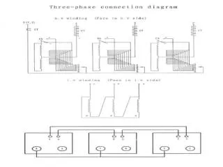
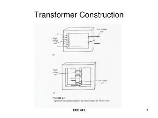
Transformer. Taking the ratio of the two equations. For an ideal transformer . Bushings Bushings are used on transformers, circuit breakers, and many other types of electric power equipment as connection points. Bushings connect outside conductors to conductors inside equipment.


Transformer
E N D
Presentation Transcript
Transformer • Taking the ratio of the two equations • For an ideal transformer
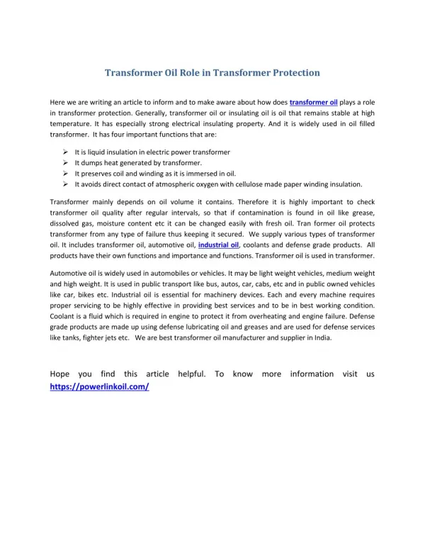
Bushings • Bushings are used on transformers, circuit breakers, and many other types of electric power equipment as connection points. • Bushings connect outside conductors to conductors inside equipment. • Bushings provide insulation between the energized conductor and the grounded metal tank surrounding the conductor. • The conductors inside the bushings are normally solid copper rods surrounded by porcelain insulation. Usually an insulation dielectric such as oil or gas is added inside the bushing between the copper conductor and the porcelain housing to improve its insulation properties. • Mineral oil and sulfur hexafluoride (SF6) gas are common dielectric materials used to increase insulation.
Regulators • For an electric utility companies it is important to provide their customers with regulated or steady voltage all the time, otherwise several undesirable conditions might occur. • Normally, residential 220 Vac is regulated to ±5% (i.e., 226 Vac ↔ 214 Vac). • For example, the first residential customer outside the substation should not have voltage exceeding 126 Vac and the last customer at the end of the distribution feeder should not have voltage less than 114 Vac. • Power companies try to regulate the distribution voltage to be within a nominal 224 Vac to 216 Vac.
Regulators…… • Customer service problems can occur if voltages are too high or too low. • For example, low voltage can cause motors to overheat and burn out. High voltages can cause light bulbs to burn out too often or cause other appliance issues. • Utility companies use voltage regulators to keep the voltage level within an acceptable or controlled range or bandwidth. • Voltage regulators are similar to transformers. • Regulators have several taps on their windings that are changed automatically under load conditions by a motor-driven control system called the load tap changer or LTC.
Regulators…… • Normally, a regulator is specified as being i.e. the distribution voltage out of the substation regulator can be raised 10% or lowered 10%. • There are 16 different tap positions on either the raising or lowering sides of the neutral position. • There is a reversing switch inside the LTC that controls whether to use the plus voltage or minus voltage direction. • Therefore, the typical voltage regulator has “33 positions” (i.e., 16 raise, 16 lower, plus neutral). • Figure 4- 18 shows the 33 positions on the dial.
Regulators…… • For example, a typical of 7200 volt, (±10% distribution regulator would have 33 tap positions. Each tap could raise or lower the primary distribution voltage 45 volts (i.e., 10% of 7200 equals 720 volts, and 720 volts divided by 16 taps equals 45 volts per tap).
Regulators…… • Reactor coils • Reactor coils are used to reduce the number of actual winding taps to eight instead of 16. • Reactor coils allow the regulator’s output contactor to be positioned between two winding taps for half the tap voltage. • Figure 4-19 shows the tap changer mechanism with the reactor coil. • Line Regulators are sometimes used near the end of long distribution feeders to reregulate the voltage to the customers downstream of the substation regulator. • Line regulators make it possible to extend the length of the distribution feeders needed to serve customers at long distances. • Figure 4-20 shows a three-phase load tap changer mechanism inside a regulator.
Circuit Breakers • The purpose of a circuit breaker is to interrupt current flowing in the transmission line, transformer, bus, or other equipment when a problem occurs and the power has to be turned off. • Current interruption can be occur for high-fault current (due to a short-circuit current or problem in the system) or simply tripped by protective relaying equipment in anticipation of an undesirable event or disturbance. • A breaker accomplishes this by mechanically moving electrical contacts apart inside an interrupter, causing an arc to occur that is immediately suppressed by the high-dielectric medium inside the interrupter. • Circuit breakers are triggered to open or close by the protective relaying equipment using the substation battery system.
Circuit Breakers • The most common types of dielectric media used to extinguish the arc inside the breaker interrupter are listed below: • Oil (clean mineral) • Gas (SF6 or sulfur hexafluoride) • Vacuum • Air • Compared to fuses, circuit breakers have the ability to open and close repeatedly, whereas a fuse opens the circuit one time and must be replaced. • Breakers can interrupt very high magnitudes of current. • They can close into a fault and trip open again. They can be controlled remotely. They need periodic maintenance.
Circuit Breakers…… • Oil Circuit Breakers • The oil circuit breaker (sometimes called OCB) interrupts arcs in clean mineral oil. • The oil provides a high resistance between the opened contacts to • stop current flow. • Figure 4-23 shows an oil circuit breaker. The interrupting contacts (referred to as interrupters) are inside the oil filled tanks. • Oil circuit breakers have the ability to be used in systems that range from low to very high voltage. • Oil has a high dielectric strength compared to air. • The main disadvantage of using oil is the environmental hazard if spilled. • The oil must be filtered or replaced periodically or after a specified number of operations to ensure the oil has a high dielectric • strength.
Circuit Breakers…… • SF6 Gas Circuit Breakers • Sulfur hexafluoride gas breakers (sometimes called SF6 or GCBs) have their contacts enclosed in a sealed interrupting chamber filled with SF6 gas. • SF6 gas is a nonflammable inert gas that has a very high dielectric strength, much greater than oil. • The operating disadvantage of using SF6 gas circuit breakers is that the gas turns to liquid at –40°C or –40°F. • Maintaining correct gas pressure is also an operational concern. • Heaters are usually wrapped around the interrupter chambers in cold weather environments to maintain proper temperature and pressure. • Figures 4-25, 26, and 27 are photos of SF6 gas circuit breakers.
Circuit Breakers…… • Vacuum Circuit Breakers • Vacuum circuit breakers (VCBs) extinguish the arc by opening the contacts in a vacuum. (Vacuum has a lower dielectric strength than oil or gas, but higher than air.) • These circuit breakers are smaller and lighter than air circuit • breakers and typically are found in “metal clad” switch gear of systems under 30 kV. Figure 4-28 shows a typical vacuum circuit breaker. • The contacts are enclosed in an evacuated bottle where no rated current can flow when the contacts separate. When the breaker opens, the arc is put out simply and quickly.
Circuit Breakers…… • Air Circuit Breakers • Since the dielectric strength of air is much less than oil or SF6 gas, air breakers are relatively large and are usually found in lower-voltage installations. • Figure 4-29 shows a 12 kV air circuit breaker. The very high voltage air-blast circuit breaker (not shown) is another type of circuit breaker that is used for subtransmission voltages. • Air-blast breakers direct a compressed blast of air across the interrupting contacts to help extinguish the arc. • Most air-blast circuit breakers are considered old or obsolete and have been replaced.
Reclosers • Similar to circuit breakers, reclosers provide circuit breaker functionality and they also include basic system-protective relaying equipment to control the automatic opening and reclosing of power circuits. • Reclosers are most commonly used on distribution systems or in smaller substations having low fault currents.. • They offer cost advantages over standard circuit breakers that require separate protective relaying equipment. • The recloser’s incorporated protective relaying equipment can be programmed to trip at specific overcurrent conditions and reclose at specific time intervals. • After a circuit trip and a programmable time delay, the recloser automatically reenergizes the circuit.