Commissioning and Initial Operating Experience with the SNS Accelerator Complex
410 likes | 519 Views
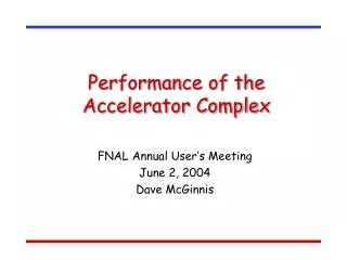
Commissioning and Initial Operating Experience with the SNS Accelerator Complex. First Beam on Target, First Neutrons and Technical Project Completion Goals Met April 28, 2006 . Beam and Neutronics Project Completion goals were met 10 13 protons delivered to the target

Commissioning and Initial Operating Experience with the SNS Accelerator Complex
E N D
Presentation Transcript
Commissioning and Initial Operating Experience with the SNS Accelerator Complex
First Beam on Target, First Neutrons and Technical Project Completion Goals Met April 28, 2006 • Beam and Neutronics Project Completion goals were met • 1013 protons delivered to the target • The SNS Construction Project was formally Completed in June 2006 • We have officially started SNS Operations
SNS Accelerator Complex Accumulator Ring Collimators Front-End: Produce a 1-msec long, chopped, H- beam Accumulator Ring: Compress 1 msec long pulse to 700 nsec 1 GeV LINAC Injection Extraction RF Liquid Hg Target RTBT 2.5 MeV 87 MeV 186 MeV 387 MeV 1000 MeV Ion Source HEBT DTL RFQ SRF,b=0.61 SRF,b=0.81 CCL Target Chopper system makes gaps 945 ns mini-pulse Current Current 1 ms macropulse 1ms
SNS High-Level Design Parameters Ring is designed for 2 MW at 1 GeV; installed for 1.3 GeV (mostly)
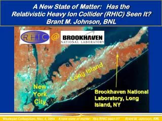
The SNS Partnership ORNL Accelerator Systems Division responsible for integration, installation, commissioning and operation
Front-End Systems • Front-End H- Injector was designed and built by LBNL • 402.5 MHz Radiofrequency quadrupole accelerates beam to 2.5 MeV • Medium Energy Beam Transport matches beam to DTL1 input parameters • Front-end delivers 38 mA peak current, chopped 1 msec beam pulse • H- Ion Source has been tested at baseline SNS parameters in several endurance runs • >40 mA, 1.2 msec, 60 Hz
Accumulator Ring and Transport Lines • Designed and built by Brookhaven National Lab Collimation Accumulator Ring Extraction Injection Circum 248 m Energy 1 GeV frev 1 MHz Qx, Qy 6.23, 6.20 x, y -7.9, -6.9 Accum turns 1060 Final Intensity 1.5x10¹⁴ Peak Current 52 A RF Volts (h=1) 40 kV (h=2) 20 kV Injected p/p 0.27% Extracted p/p 0.67% RF RTBT HEBT Target
Ring and Transport Lines HEBT Arc Ring Arc Injection RTBT/Target
Target Region Within Core Vessel Target Module with jumpers Outer Reflector Plug Target Moderators Core Vessel water cooled shielding Proton Beam Core Vessel Multi-channel flange
Normal Conducting Linac: Front-End Output Emittance and Bunch Length • MEBT inline emittance system allows routine measurement • Expect 0.3 mm mrad, rms, norm • Results ( mm mrad, rms, norm) • X = 0.29 • Y = 0.26 • Bunch length measured with mode-locked laser system RMS Bunch Length (deg) Rebuncher phase (deg)
DTL and CCL RF Setpoints by Phase Scan Signature Matching J. Galambos, A. Shishlo • To tune up the linac requires finding phase and amplitude setpoints for 95 RF systems within 1%/1 deg (specification) • Model-based methods utilizing time-of-flight data have been developed • Normal conducting linac phase and amplitude setpoints determined by Phase-Scan Signature Matching • Plot shows data (lines) compared to model (pts) for two CCL2 amplitudes BPM Phase Diff (deg) CCL Module 2 RF Phase
CCL Module 1 Longitudinal Bunch Shape Monitor Measurements BSM107 BSM111 • Measured values are close to the predicted bunch length • Measurements were motivated by earlier observations of a longer bunch, presumably due to longitudinal mismatch
Superconducting Linac Tuneup by Phase Scan SCL phase scan for first cavity Solid = measured BPM phase diff Dot = simulated BPM phase diff Red = cosine fit • Fit varies input energy, cavity voltage and phase offset in the simulation to match measured BPM phase differences • Relies on absolute BPM phase calibration • With a short, low intensity beam, results are insensitive to detuning cavities intermediate to measurement BPMs BPM phase diff Cavity phase
Low-level RF Feedforward • Beam turn-on transient gives RF phase and amplitude variation during the pulse, beyond bandwidth of feedback • LLRF Feedforward algorithms have been commissioned (Champion, Kasemir, Ma, Crofford) Without Feed-forward With Feed-forward
SCL Operations: Fault Recovery (Galambos) • We have successfully tested a cavity fault recovery algorithm in which the phase of all downsteam cavities are adjusted in response to a change in setpoint of a given cavity Turned on cavity 4a, reduced fields in 11 downstream cavities Final cavity phase found within 1 degree, output energy within 1 MeV Cavity 3a turned off
Ring/RTBT/Target Commissioning Timeline January-May 2006 Jan. 12: Received approval for beam to Extraction Dump. Jan. 13: First beam to Injection Dump. Jan. 14: First beam around ring. Jan. 15: >1000 turns circulating in ring Jan. 16: First beam to Extraction Dump. Jan. 26: Reached 1.26E13 ppp to Extraction Dump. Feb. 11: ~8 uC bunched beam (5x10¹³ ppp) Feb. 12: ~16 uC coasting beam (1x10¹⁴ ppp) Feb. 13: End of Ring commissioning run April 3-7: Readiness Review for RTBT/Target April 27: Received approval for Beam on Target April 28: First beam on target and CD4 beam demonstration
Accumulation and Extraction of 1.3x10¹³ protons/pulse (January 26, 2006) Ring Beam Current Monitor extraction 200 turn accumulation Extraction Dump Current Monitor
Ring Orbit Correction: H,V Bumps are Due to Injection Kickers Horizontal Orbit Vertical Orbit BPM Amplitude
Ring Optics Measurements: Betatron Phase Advance and Chromaticity Plots show measured betatron phase error vs. model-based fit Data indicates that the linear lattice is already very close to design
High Intensity Studies (Danilov, Cousineau, Plum) Fast: electron-proton • Beam intensity records (protons/pulse): • 5x10¹³ in bunched beam, transported to target • 1x10¹⁴ unbunched, coasting beam • We searched for instabilities by i) delaying extraction, ii) operating with zero chromaticity, iii) storing a coasting beam • No instabilities seen thus far in “normal” conditions • See instability centered at 6 MHz, growth rate 860 us for 1014 protons in the ring, driven, as predicted by extraction kicker impedance • Zcalc22-30 kOhm/m • Zmeas 28 kOhm/m. • In coasting beam also see very fast instability at 0.2-1x10¹⁴ protons in the ring, consistent with e-p. Growth rate 20-200 turns. f 30-80 MHz depending on beam conditions. • Scaling these observations to nominal operating conditions predicts threshold > 2 MW for extraction kicker (as previously predicted) Slow: Extraction Kicker
Phase Space Painting Stripping Foil Initial Closed Orbit Injected Beam Final Closed Orbit px X Wei et. al., PAC 2001, 2560 X-Y space after 1060 Turns
Phase Space Painting Beam on Target View Screen Beam profiles in RTBT 65 mm 80 mm
Beam-Power-on-Target History Beam power administratively limited to 10 kW until November 8 Beam Power [0-65 kW] May 1, 2006 Feb 1, 2007
FY 2007 Integrated Beam Power by Day and Cumulative • 6.3 MW-hrs delivered in Run 2007-1
Technical Challenges: Equipment Reliability • Beam Chopper Systems • Repeated failures in Low-energy and Medium-energy Beam Transport chopper systems • New, more robust, designs will be designed and manufactured this year (FY07 Accelerator Improvement Project) • High-Voltage Converter Modulators • A number of weak components limit MTBF to 2700 Hrs • Several prototype improvements are in test in single operational units • Improvements will be deployed this year on full system of 14 modulators (FY07 Accelerator Improvement Project) • Ion Source and Low Energy Beam Transport System • Water Systems • Problems associated with clogging flow restrictors, failed gaskets, poor conductivity monitoring and control, etc. • Reliability improvements have been underway since CD-4 (also FY07 AIP) • Cryogenic Moderator System • Thermal capacity degraded in 3 week cycle prior to December 2006 • Manufacturer attempted repair in December • Capacity improved, but some sign of degradation remains • Mercury Pump • Seal failed end of November • Operating the pump now with failed seal, mitigated by installation of a cover plate to direct gas to the Mercury Off-Gas Treatment System • Replacement Mercury Pump in expected to be available for installation in September
Technical Challenges: Beam Power • Beam losses must be kept below 1 Watt/m to limit residual activation • We measure higher than desired losses in the Ring Injection area • We are unable to simultaneously transport waste beams (from stripping process) to the injection dump and properly accumulate in the ring • Internal Review of Injection Dump performance was held in November and follow-up meeting in December • Short-term fixes allow >100 kW operation; mid-term fixes (April 2007) are in preparation; long-term fix requires redesign of injection dump beamline and 2 new magnets • An aggressive accelerator physics program has reduced losses and activation while allowing increased beam power • We are not operating 9 Superconducting RF cavities (out of 81) out of concern for potential failures • Recent tests indicate that 6 of these 9 cavities are operable up to 15 Hz repetition rate • Those tests also show that the behaviour of individual cavities is the same at higher repetition rates, up to the full 60 Hz • We are building infrastructure to provide cryomodule repair and maintenance capabilities on-site. We are formulating plans to restore operation of all cavities, and to procure spare cryomodules
Outlook: Performance Goals FY07 FY08 FY09 • SNS Beam Power Upgrade Project will increase linac output energy to 1.3 GeV and provide 3 MW beam power
E-P Feedback Experiment at the PSR • We formed a collaboration to carry out an experimental test of active damping of the e-p instability at the LANL PSR (ORNL, LBNL, IU, LANL) • We deployed a broadband transverse feedback system designed and built by ORNL/SNS and demonstrated for the first time damping of an e-p instability in a long-bunch machine • We observed a 30% increase in e-p instability threshold with feedback on.
Laser-Stripping Injection Proof-of-Principle Experiment Laser Beam High-field Dipole Magnet High-field Dipole Magnet H- H0 H0* proton Step 1: Lorentz Stripping Step 3: Lorentz Stripping Step 2: Laser Excitation H- H0 + e- H0 (n=1) + H0* (n=3) H0* p + e- • We have observed > 90% H- to proton stripping efficiency in proof-of-principle tests at SNS H- to protons
Yes, We’ve Had a Few Surprises • RFQ resonant frequency shifted by 100 kHz • Never found the cause; retuned in 2003 • Bunch length 3x design in CCL1; also had difficulty keeping DTL5 at design field • Found a charred piece of paper in DTL Tank 5 in 2004 • Large local losses and poor trajectory near SCL/HEBT transition • Found large dipole deflection with orbit response studies • Found current shunted around one quad coil • Beam is rotated about 6 degrees on target view screen • Excessive fundamental power through two SCL HOM feedthroughs; others impacted • Large local losses in injection dump line
Summary • Completed 7 beam commissioning runs, amounting to more than 1 year of dedicated beam commissioning and operating time • Achieved beam and neutron project completion requirements within project schedule • SNS construction project was formally completed in June 2006 on-budget and on-schedule • We are now in the early operations stage with local users • We are beginning to ramp up the beam power of the SNS accelerator complex
SNS Beam Diagnostic Systems RING 44 Position 2 Ionization Profile 70 Loss 1 Current 5 Electron Det. 12 FBLM 2 Wire 1 Beam in Gap 2 Video 1 Tune MEBT 6 Position 2 Current 5 Wires 2 Thermal Neutron 3 PMT Neutron 1 fast faraday cup 1 faraday/beam stop D-box video D-box emittance D-box beam stop D-box aperture Differential BCM Operational IDump 1 Position 1 Wire 1 Current 6 BLM Not Operating EDump 1 Current 4 Loss 1 Wire CCL 10 Position 9 Wire 8 Neutron, 3BSM, 2 Thermal 28 Loss 3 Bunch 1 Faraday Cup 1 Current RTBT 17 Position 36 Loss 4 Current 5 Wire 1 Harp 3 FBLM DTL 10 Position 5 Wire 12 Loss 5 Faraday Cup 6 Current 6 Thermal and 12 PMT Neutron SCL 32 Position 86 Loss 9 Laser Wire 24 PMT Neutron HEBT 29 Position 1 Prototype Wire-S 46 BLM, 3 FBLM 4 Current LDump 6 Loss 6 Position 1 Wire ,1 BCM CCL/SCL Transition 2 Position 1 Wire 1 Loss 1 Current
Baseline SNS Ion Source Performance Our Best Run (employs new operating procedure) 3 Typical Test Runs Catastrophic antenna failure Run #9 ran for 16 days / 33 mA / 0.4 mA/day. Beam attenuation ~5 mA/day • LBNL H- ion source + ORNL antennas • Source performed well during SNS commissioning. • Successful commissioning would not be possible without use of longer-lived antennas. • 10-40 mA routinely delivered at ~0.1% duty-factor. • Availability improved: 86% ~100% during later commissioning periods (target comm: 77 days). • Largest availability gain redesigning LEBT insulators + Antennas: Welton et al, RSI 73 (2002) 1008 • ~10 lifetime tests performed at full 7% duty-factor and max current. • Best results shown • Outcome: Insufficient beam current, frequent antenna failures and poor beam stability with time • Vigorous R&D program to meet SNS operational requirement of 40 mA and SNS-PUP requirement of 60 mA.
Recent Ion Source R&D Accomplishments Cs injection collar Ionization Cone Extractor electrode ions Air duct Cs Line Al2O3 insulator Cooling channel Cathode Ions Plasma stream Anode Elemental Cs system • 65 mA-1.2 ms, 70 mA-0.2 ms pulses achieved at 10Hz! • ~2x increase in RF power efficiency. • Multi-day runs show excellent beam stability. • Multiple cesiations show excellent reproducibility. • ~5% droop and good ~30 us rise times. • Beam emittance is expected to be similar to baseline source. Welton et al, LINAC 2006, Knoxville External Antenna & Plasma Gun • Multi-year lifetime achieved at DESY at <1% duty-factor • Plasma gun enhances H- ~50% • 51 mA – 0.2 ms pulses achieved with no Cs and no B-field confinement. • 65 mA – 0.2 ms, 50 mA – 1.2 ms pulses achieved with Cs and no confinement. Welton et al, LINAC 2006, Knoxville
Energy Stability – Pulse to Pulse (J. Galambos) • RMS energy difference jitter is 0.35 MeV, extreme = + 1.3 MeV • Parameter list requirement is max jitter < +1.5 MeV 865 MeV beam ~ 1000 pulses 20 msec pulse 12 mA beam
SCL Laser Profile Measurements • SCL laser profiles (H + V) were available at 7 locations • 3 at medium beta entrance, 3 at high beta entrance and 1 at the high beta end Measured horizontal profile after SCL cryomodule 4
Neutrons: 4-methyl pyridine N-oxide 5 kWatt, 3 hour, ¼ detector, T = 3 K 4 meV
The Spallation Neutron Source • The SNS is a short-pulse neutron source, driven by a 1.4 MW proton accelerator • SNS will be the world’s leading facility for neutron scattering research with peak neutron flux ~20–100x ILL, Grenoble • SNS construction project, a collaboration of six US DOE labs, was funded through DOE-BES at a cost of 1.4 B$ • SNS will have 8x beam power of ISIS, the world’s leading pulsed source • Stepping stone to other high power facilities