Commissioning Experience and Status
270 likes | 440 Views
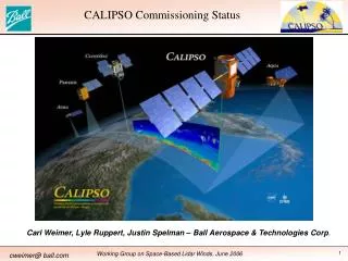
L2 installation readiness review:. Commissioning Experience and Status. Burkard Reisert (FNAL). Level 2 Upgrade System configuration. Linux PCs: decision. Pulsar pre-processors. control. L1 Muon L1 Tracks L1 Trigger decsion. PC. Muon. PC. Merger. Trigger Supervisor.

Commissioning Experience and Status
E N D
Presentation Transcript
L2 installation readiness review: Commissioning Experience and Status Burkard Reisert (FNAL)
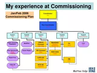
Level 2 Upgrade System configuration Linux PCs: decision Pulsar pre-processors control L1 Muon L1 Tracks L1 Trigger decsion PC Muon PC Merger Trigger Supervisor Cluster SLINK L2 CALO (Cluster/ IsoCluster) Energy Sums SLINK-PCI L2toTS SVT SVT Electron Shower Max Phase I: single PCconfiguration Phase II: dedicated PC for each L2 buffer Merger Strategy: Commission parasitically need to split all input signals (fiber + LVDS)
Pulsar Board VME interface FPGAs DataIO connectors for all LVDS interfaces of legacy input systems (Rx & Tx) FPGA Data merging & control L1 decision & Tracks visible to all 3 FPGAs mezzanine card Connectors (optical fiber interfaces) Slink interface
MOAB (Mother of All Boards) AUX Card Pulsar TAXI works up to 100 MHz CERN SLink HOTLINK Initial checkout ALL interfaces: ~ 2 people in ~ 1 month Design& Verifications: ~ 3 people in ~ 9 months Custom mezzanine cards types: 2 Rx for L2 System 2 Tx for test stand Result: No blue wire on all prototypes All prototypes became production boards
Hardware counts Pulsar boards: 59 10 Level2 systems ( 1 (Run IIa) + 9 (Run IIb)) 22 for SVT RW (15), SVT upgrade dev (5) , XFT upgrade (2) Hotlink Rx: 17 fiber + 5 Hotlink+lvds 4+5 (Run IIa + IIb) + 1lvds (Run IIb) Hotlink Tx: 17 fiber + 5 Hotlink+lvds Taxi Rx: 42 14 (Run IIb) Taxi Tx: 22 AUX Card: 3.3V: 20, 5V: 5 8 (Run IIb) Slink LDC/LSC Hola: 19 pairs 9 pairs (Run IIb) Slink S32PCI64: 6 3 (Run IIb) Note: Apply factor 1-1.5 to run IIb needs to avoid hardware shortage for development & commissioning
Testing • Hardware testing • board checkout with standalone VME code • Firmware testing • run control driven Tx Rx (slink formatter) Slink Rx • - calib continuous, normal mode/myron mode ,L2 Auto/L1 Alt • rates ~< 2kHz • - test stand sparky setup random trigger sequence • dial L1 and L2 accept rate upto 30kHz L1 • Cosmic and L2 torture • Parasitic beam tests • Dedicated beam tests
Test Stand for Production Testing • Using: • dedicated Test firmware • standalone c-code • Tested features: • VME access • Internal RAM and SRAM • Internal communication • TS interface • SVT/XTRP • L1 Signals • Mezzanine card • Interface • Slink Interface • Documented by • Angie Little Tx Rx Mezz. L1 Mezz. TS L1 Mezz. Mezz. SVT/XTRP SLINK AUX
Muon Rx Firmware • Select data that is actually • used in L2 decisions • Zero suppress muon data • Inputs: • hotlink fibers • muon matchbox & • prematch box • L1 Trigger bits • XTRP cable Slink formatter: 1 package Containing L1 bits, Track data, zero suppressed Muon data Diagnostic DAQ Buffers Muon inputs on DataIO FPGAs XTRP input and Slink output on Control FPGA ~ 1 month of parasitic running, no problems found (low level bit errors (1 in >100,000) proven to be upstream)
SVT Rx Firmware • Select data that is actually • used in L2 decisions (ala TL2D) Inputs: SVT cable (VTM from SRC) Slink formatter: 1 package SVT data Timing of input data for Current and previous event, begin and end of package Diagnostic DAQ Buffers SVT Input and Output on Control FPGA ~ 1 month of parasitic running, no problems found
Reces Rx Firmware (3 boards) implemented algorithm: pass on all data (will change to zero suppression to meet latency goal: non SVT data < SVT data in all events) Inputs: 16 TAXI fibers Note: Control FPGA Identical to Slink merger Slink formatter: 1 package RECES data Diagnostic DAQ Buffers Fiber Inputs on DataIO FPGAs Slink output on Control FPGA ~ 3 weeks of parasitic running, see Chris talk for known features
Slink Merger Algorithm: Merge up to 4 inputs, which are enabled through register Record all inputs Inputs: Up to 4 Slink inputs (HOLA LDC) Note: Timing of input data for Current and previous event, begin and end of package ( last store) Slink formatter: 1 output Slink package Diagnostic DAQ Buffers Slink Inputs on DataIO FPGAs Slink output on Control FPGA ~ 2 weeks of parasitic running (core firmware), no errors found
Level2 to Trigger supervisor Algorithm: Record return message from CPU Handshake with TS Inputs: 1 Slink LDS (from CPU) TS Interface cable Note: Global timing info L1A L2A/R Start and end of TS handshake Note: Timing of input data for Current and previous event, begin and end of package ( last store) Diagnostic DAQ Buffers CPU return on DataIO FPGA(s) Global timing on Control FPGA ~ 3 weeks of parasitic running (core firmware), no errors found
DAQ readout (TP2D bank) • Each pulsar board (Muon/SVT/RECES/Cluster/Merger/L2toTS) • provides a lot of diagnostic information. • use a very flexible readout configuration to keep readout times low • Only readout selected boards • enable/disable single DAQ buffers • fixed length or variable length readout • board level readout list • Readout configured through Hardware database parameters
Solution: more flexible Readout Configurartion: New parameters Dial number of words per DAQ RAM Board level Readout list Deal with remapped Fiber Input DAQ Thanks to Bill & Jane
A Parallel Universe for the Pulsar Fiber Splitter Lab Hotlink Rx Hotlink Tx Tracks SVT Taxi Tx SVT Taxi Rx L2 Muons 1/3 RECES Power meter CList ISOList Muon splitters LVDS Fanout board Reces Cluster • Optical • LVDS • Splitters Legacy Level 2 Decision Crate a - Processor
PULSAR Configuration for Initial Beam Test Linux PC Trigger Supervisor L1 muon L1 track L1 bits Muon • Control node • monitor info • interact with RC L2toTS SVT SVT Goal: Demonstrate the full chain Input Data Pulsar Receiver Slink/PCI CPU PCI/Slink L2toTS CPU running some simple algorithms based on L1/Muon/XTRP/SVT Test runs: Pulsar and Alpha driving the system with same trigger table Smooth Operation w/o Silicon and w/ Silicon L=20E30; L1A 14kHz L2A~60Hz
PULSAR System Configuration in Beam Tests Linux PC L1 muon L1 track L1 bits Trigger Supervisor SLINK Muon Merger SLINK Cluster SlinkTx SLINK L2toTS realistic test pattern SVT SLINK ShowMax (Reces) 1/3 Data 2/3 Tx SVT Goal: Experience in realistic environment Test complete Pulsar L2 System Test runs: Pulsar and Legacy L2 (Alpha) driving the system Smooth Operation L=60E30; L1A 21kHz, L2A~100Hz Electron RecesTx Merger SLINK
Beam Tests August 2004 Test data taking with a subset of Triggers (using Muon, Track and displaced Vertex) 1) Legacy L2 making the decision Pulsar system running parasitically 2) Pulsar making the decision Perfect match of trigger decisions Of both systems before and after prescales
PULSAR System Timing Measurements Pulsar pre-processors Linux PC L1 Muon L1 Tracks L1 Trigger decsion Muon Merger Trigger Supervisor Merger inputs Cluster SLINK L2 CALO (Cluster/ IsoCluster) Energy Sums SLINK-PCI L2toTS SVT Decision SVT Handshake with TSI & L1AL2A/R Electron Shower Max SVT input Merger buffer specific counters on L1A - current event - previous event (unbiased)
System timing measurements Overall L1A to L2 Decision latency New system (not optimized) already as fast as CDF Legacy Level2 Timing measurements give guideline for optimization. Goal: latency nonSVT<SVT Alpha L2 Legacy <44 ms> ms Pulsar (on first shot) CPU: Xenon CPU: AMD will be faster Silicon Vertex Trigger Tail due to Silicon Vertex Trigger processing time ms
Decision returned, Handshake TS, Global L2A/R (previous event) -- Decision returned -- TS handshake starts -- TS handshake ends -- Global L2 Decision (broadcasted on back plane) Dt = 0.8 ms (will be reduced) Dt = 0.6 ms Dt = 1.7 ms
System timing measurements Muon/Tracks/L1 Silicon Vertex Trigger ms ms • Provide very valuable guide line • for system optimization: • e.g. • - SVT on separate Slink to PCI path • - select subsystem path to optimize first • (Muon/Tracks/L1 vs. ShowerMax) Shower Max (Electron) ms
Latencies in Reces Data Path Reces Data arriving at Reces Rx: Reces Data arriving at Merger L1A 8 ms 15 ms ShowMax (Reces) Reces Merger “final” Merger Reces Rx SLINK SLINK Room for improvements: -- reduce overhead in RecesRx state machines -- zero suppress Reces Data -- optimize Merger Total reduction of Reces Path latency > 3ms
Summary • Hardware is in good shape • Firmware is in reasonable shape, • needs fine tuning/testing in some cases • Commissioning • an impressive amount of results has been achieved • we were very productive as a team,we need to keep the momentum going to meet the goal: • “commissioning in March 2005”
MUON RECES RECES RECES SVT C LU L2 toTS MERGER MERGER One picture worth a thousand words: LEVEL2_PULSAR_00 crate
Physics table PULSAR_TEST_v-1 Physics table PULSAR_TEST_v-1 More details on the trigger table Special Trigger table based on L1/Muon/XTRP & SVT inputs Pulsar and Alpha Decision agree Identical rates