Download
1 / 20
200 likes | 299 Views
Explore construction, translation, and assessment of formal models for PLC programs to enhance safety levels. Investigate impact of IEC 61508 standard, design controllers for power plants & steam turbines.

E N D
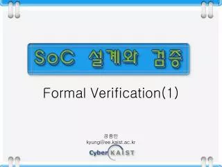
Efficient representation for formal verification of PLC programs Vincent Gourcuff, Olivier de Smet and Jean-Marc Faure LURPA – ENS de Cachan
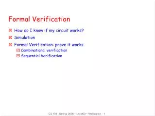
Outline • Objective of the work • Construction of formal models • Representation construction • Dependencies analysis • Translation of PLC programs into formal models • Assessment of the representation efficiency • Conclusions and prospects
Objective Design of controllers for critical systems Requirements Power plant ? Refinery Control system Steam turbine
Objective Impact of the IEC 61508 standard • Functional safety of E/E/PE safety-related systems • Industrial need: to reach the SIL3 or SIL4 levels (SIL: Safety Integrity Level) • Hardware: redundancies, voting mechanisms, …. • Software: recommendations for development • SIL levels and software development
Objective Overall objective • To investigate the possibilities of formal verification for improving the SIL level of critical systems controlled by PLCs
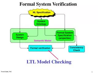
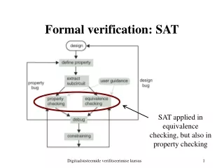
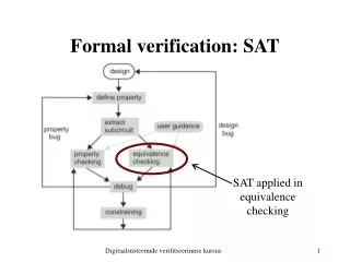
Construction of formal models Requirements Formal verification of PLC programs Scheduler Program • O1 := I1 OR I2; • O2 := I3 AND I4; • IF O1 • THEN • O3 := I3 AND NOT(I4); • END_IF; • O4:= RS(O5,I1) • O5 := O2 AND O4; • O1 := NOT(I2 OR I4); Initialization Informal extrinsic (application-dependant) properties Inputs reading 1 Program execution Formalization Outputs updating 2 Formalization AG (( dp_head_motor_up) => EF (!dp_head_motor_up )) Formal representation Formal representation Model – Checker [Rausch Krogh 98] [Frey Litz 00] [de Smet Rossi 02] [Huuck Lukoschus Bauer 03] … Property proved or counterexample 3
Construction of formal models Technical barriers when model-checking PLC programs 1 2 3
Formal representations Collection of automata 5-tuple { S, Σ, Λ, T, G } : 3 finite sets : states (S) input alphabet (Σ) output alphabet (Λ) a transition function (T : S × Σ → S) an output function (G : S → Λ). Transition relations on variables Equations system: VARn+1 = F(VARn) VARn+1 the set of variables, at the next step of calculus VARn the set of variables, at the current step of calculus Temporal logic statements CTL LTL Real world behavior Construction of formal models PLC Initialization Inputs reading Program execution Outputs updating Process What is the meaning of a state ? Cyclic scheduler Program Variables states Execution state IF O1THENO3 := I3 AND NOT(I4);END_IF; ? Expected and unexpected states and sequences Requirements
Construction of formal models PLC program O1 • O1 := I1 OR I2; • O2 := I3 AND I4; • IF O1 • THEN • O3 := I3 AND NOT(I4); • END_IF; • O4:= RS(O5,I1) • O5 := O2 AND O4; • O1 := NOT(I2 OR I4); I1 O2 I2 O3 I3 O4 I4 O5 PLC scheduler Initial state Case of a PLC program I1=1, I2=0, I3=1, I4=0, O1=0, O2=1, O3=0, O4=0,O5=1 Inputs reading I1=0, I2=0, I3=1, I4=0 I1=0, I2=1, I3=1, I4=0 O1=0 O2=0 O4=1 O5=0 O1=1 Outputs updating I1=1, I2=0, I3=1, I4=0, O1=1, O2=0, O3=0, O4=1,O5=0 I1=1, I2=0, I3=1, I4=0, O1=1,O2=0,O3=0,O4=1,O5=1 PLC cycle 1 PLC cycle 2
Representation construction Features of the considered programs • PLC programs are executed sequentially; • only Boolean variables are used; • internal variables may be included in the program; • only the following statements of the ST language are allowed: • assignment; • Boolean operators defined in IEC 61131-3 standard (NOT, AND, OR, XOR) • function block (FB) (IEC 61131-3 standard or user-made) • control statements, IF and CASE selection statements; • iteration statements (FOR, WHILE, REPEAT) are forbidden; • multiple assignments of the same variable are possible.
Representation construction PLC program Formal model design NuSMV model Global method Static analysis O5 Static dependencies I1 O4 O4 Taking into account execution order O5,i Temporal dependencies I1,i+1 O4,i+1 O4,i
I1,i+1 O1 I1 O1 Static and temporaldependencies construction I2,i+1 I2 I3,i+1 O2,i+1 I3 O2 I4,i+1 I4 I1,i+1 O1 I2,i+1 O3 O3,i O3,i+1 O3 I3 I3,i+1 I4 I4,i+1 O5 O5,i I1 O4 I1,i+1 O4,i+1 O4 O4,i O2 O5 O2,i+1 O5,i+1 O4 O4,i+1 I2 O1 I2,i+1 O1,i+1 I4 I4,i+1 Static dependencies Temporal dependencies
Representation construction Translating ST controllers into NuSMV models:general algorithm BEGIN PLC_prog_TO_NuSMV_model(Pr) FOR each statement Si of Pr: IF Si is an assignment (Vi := expressioni) THEN FOR each variable Vk in expressioni: Replace Vk by the variable pointed out in the temporal dependency (Vk,i or Vk,i+1) ELIF Si is a conditional structure (if cond; then stmt1; else stmt2) FOR each variable Vk in cond: Replace Vk by the variable pointed out in the temporal dependency (Vk,i or Vk,i+1) FOR each variable Vm assigned in Si : Replace Vm assignment by: ”case cond : assignment of Vm in PLC_prog_TO_NuSMV_model(stmt1); !cond : assignment of Vm in PLC_prog_TO_NuSMV_model(stmt2); esac ; ” ASSIGNMENT CONDITION CONDITIONAL STRUCTURE STATEMENT
Representation construction Translating ST controllers into NuSMV models:example Next(I1) := {0, 1}; Next(I2) := {0, 1}; Next(I3) := {0, 1}; Next(I4) := {0, 1}; Next(O2) := Next(I3) & Next(I4); Next(O3) := case Next(I1) | Next(I2) : Next(I3) & !(Next(I4)); !(Next(I1) | Next(I2)) : O3; esac; Next(O4) := case Next(I1) : 0; O5 : 1; 1 : O4; esac; Next(O5) := Next(O2) & Next(O4); Next(O1) :=!(Next(I2) | Next(I4)); + Temporal dependencies From generic models library O5,i I1,i+1 O4,i+1 O4,i
Representation construction Translating ST controllers into NuSMV models: comparison to previous approaches Next(I1) := {0, 1}; Next(I2) := {0, 1}; Next(I3) := {0, 1}; Next(I4) := {0, 1}; Next(O2) := Next(I3) & Next(I4); Next(O3) := case Next(I1) | Next(I2) : Next(I3) & !(Next(I4)); !(Next(I1) | Next(I2)) : O3; esac; Next(O4) := case Next(I1) : 0; O5 : 1; 1 : O4; esac; Next(O5) := Next(O2) & Next(O4); Next(O1) :=!(Next(I2) | Next(I4)); No intermediary variables states No "line_counter" because the execution state is no more useful No "end_of_cycle" variable; one cycle is reduced to only one state
Efficiency assessment PLC program O1 • O1 := I1 OR I2; • O2 := I3 AND I4; • IF O1 • THEN • O3 := I3 AND NOT(I4); • END_IF; • O4:= RS(O5,I1) • O5 := O2 AND O4; • O1 := NOT(I2 OR I4); I1 O2 I2 O3 I3 O4 I4 O5 PLC scheduler Basic example Comparison of the state spaces sizes • state space reduction (about 15 times) • reduction of the maximum distance between states (system diameter) (11 times shorter) • indirect consequence : trace of counterexample reduced
Efficiency assessment Fishertechnik example [Special session at ACC02] • known tested machining line • already written control program • expected behavior known • small scale system • 15 Inputs • 15 Outputs • Comparison of the proof process durations
Conclusions • Efficiency of the representation assessed • Translation of PLC programs • Fully automated • Fast (some seconds or tens of seconds for industrial programs) On-going works • Improvement of the representation efficiency by limiting the number of stored variables • Taking into account integer and real variables • Design of a library of tailor-made function blocks
Efficient representation for formal verification of PLC programs Thank you for attention
State distance • d(1,2) = 1 • d(1,3) = 2 • ... • d(2,1) = 2 • ... • System diameter • SD = max (d(I,j)) = 2 2 3 1 4