Download
1 / 28
280 likes | 398 Views
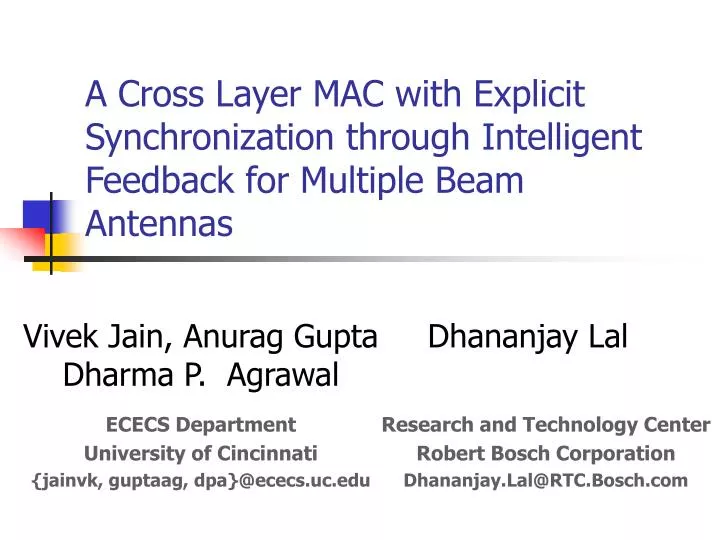
A Cross Layer MAC with Explicit Synchronization through Intelligent Feedback for Multiple Beam Antennas. Vivek Jain, Anurag Gupta Dharma P. Agrawal. Dhananjay Lal. ECECS Department University of Cincinnati {jainvk, guptaag, dpa}@ececs.uc.edu. Research and Technology Center

E N D
A Cross Layer MAC with Explicit Synchronization through Intelligent Feedback for Multiple Beam Antennas Vivek Jain, Anurag Gupta Dharma P. Agrawal Dhananjay Lal ECECS Department University of Cincinnati {jainvk, guptaag, dpa}@ececs.uc.edu Research and Technology Center Robert Bosch Corporation Dhananjay.Lal@RTC.Bosch.com
Outline • Introduction • Multiple Beam Antennas • MAC Protocol Design Issues • The ESIF Protocol • Performance Evaluation • Conclusions
Directional Antenna – Better Spatial reuse. But a node still unable to fully utilize “spatial bandwidth”. Nodes in Silent Zone E C C G G X A B A B F H F D H D Directional Communication Introduction Omnidirectional Antenna – Low Throughput in Wireless Ad hoc networks due to poor spatial reuse Omnidirectional Communication
DATA DATA DATA DATA DATA DATA Introduction • Multiple Beam Antenna – Exploits spatial bandwidth fully • A node can initiate more than one simultaneous transmissions (or receptions). A E D B F C G
Interferer 3 top view (horizontal) top view (horizontal) Interferer 3 3 4 User 3 2 5 Interferer 1 Interferer 1 User 3 6 1 User 1 User 1 7 12 8 11 9 10 Interferer 2 User 2 User 2 Interferer 2 Switched array Adaptive array Wireless Local Area Networks Cellular Communication Networks Military networks Applications Multiple Beam Antennas - Types
Beam Formation Direction of Arrival Estimation Multiple Beam Antennas - Beam Forming Therefore, a node can either transmit or receive simultaneously but not both. … …
IEEE 802.11 DCF • De-facto medium access control for wireless LAN and ad hoc networks • Originally designed for omnidirectional communication, its virtual carrier sensing (VCS) mechanism is enhanced for directional communication to include directional of arrival also. Physical Carrier Sensing DIFS SIFS Time RTS Data Source SIFS SIFS CTS ACK Destination DIFS RTS NAV (RTS) Other NAV (CTS) aSlotTime NAV (Data) Virtual Carrier Sensing Defer access RandomBackoff
DIFS RTS RTS RTS RTS RTS RTS DIFS RTS RTS DATA CTS RTS DIFS ACK CTS MAC – Issues Concurrent Packet Reception with IEEE 802.11 DCF A E DIFS D B F C G Conclusion: Eradicate the backoff after DIFS duration
DATA ACK RTS CTS MAC Issues – Backoff Removal • Multiple transmitters, located in the same beam of common receiver, always get the same receiver schedule and thus initiate communication at the same time - collision • A node with very high data generation rate will overwhelm its receiver, without giving latter a chance to forward this traffic - fairness issue • All classes of service get same priority – QoS issue Use p-persistent CSMA A DIFS RTS X RTS B C DIFS A B C DIFS DIFS Hold the transmitting node
ESIF – Assumptions • Nodes are equipped with multiple switched beam antenna array and can precisely calculate the Angle of Arrival (AoA) of the received signal • All nodes form non-overlapping multiple beams with equal gain so as to collectively span entire space • Beam shape is assumed as conical and benefits of nulling or the impact of side-lobe interference are not considered • A node can either transmit or receive data on multiple beams at the same time but not both • The channel is symmetric.
ESIF – ENAV • Every node maintains an ENAV: • The beam a neighbor falls within • Neighbor’s schedule - the duration until this neighbor is engaged in communication elsewhere • Whether a neighbor’s schedule requires maintaining silence in the entire beam • Number of data packets outbound for the neighbor • The p-persistent probability to use when talking to this neighbor
ESIF – Cross Layer Data Management • Using network layer information along with ENAV a node determines: • Whether a beam contains an active route • The number of potential transmitters in each beam • Until what time the node needs to maintain silence in a particular beam • Each node has a store-and-forward buffer for relaying data packets • Available buffer is used dynamically to form different queues for each beam - prevents head-of-the-line blocking
ESIF – Design • ESIF piggybacks feedback onto control messages; RTS with Intelligent Feedback (RIF), and CTS with Intelligent Feedback (CIF), Schedule Update with Intelligent Feedback (SCH) • SCH identifier allows a neighbor to adjudge whether to defer transmission for only this node or for the entire beam • buffer-threshold to control priorities between receiver and transmitter modes • Reception gets priority as long as the buffer size remains under the threshold • If a node cannot actually initiate transmitter mode, the receiver still gets the priority • Priority switch solves problems of an overwhelmed receiver. • This also provides a mechanism to control the contribution of a node to end-to-end delays
ESIF – Control Message Packet Format • Type field in Frame Controlis used toidentify a control message as RIF, CIF or SCH • Duration holds the estimated time of communication that the other nodes must backoff for; • Priority contains the priority of this request, and • p is the persistent probability which the other nodes should use when talking to this node. Control packet (RIF/CIF/SCH) format
3 2 4 1 Directional Coverage Area 5 8 Omnidirectional Coverage Area 6 7 Performance Evaluation • Generation of packets is modeled as a Poisson process with the equal mean arrival time • IEEE 802.11 DCF based protocols are used for omnidirectional antenna (Omni), single beam directional antenna (Directional-NB) and MBAA (MMAC-NB), directional (Directional) and multiple-beam (Multibeam) • Directional-NB, MMAC-NB and ESIF protocols involve DVCS • ESIF is implemented with a buffer-threshold value of 1 Gains from spatial reuse only are considered The Antenna Model
Performance Evaluation B A • Removal of contention window based backoff in ESIF does not affect long-term fairness • Both the transmitters get equal opportunity to transmit
A C B D Performance Evaluation • ESIF enhances throughput by the priority switch between transmission and reception modes • ESIF is able to achieve concurrent data communications between node pairs A-B and C-D
A E D B F C G Performance Evaluation • ESIF is able to achieve CPR at common intermediate node D • Dynamic priority switch ensures data packets just received are transmitted (concurrently) in the next cycle, thus, maximizing throughput and minimizing delay
Conclusions • ESIF is the first attempt to achieve concurrent packet reception with on-demand protocols for MBAA • ESIF removes the contention window based random backoff in IEEE 802.11 DCF based protocols and uses embedded feedback to synchronize neighboring nodes • Allows nodes to receive or transmit multiple packets simultaneously in different beams • Cross layer information is used to guarantee long-term fairness • ESIF is a hybrid of synchronous and asynchronous on-demand medium access control
Questions ??? Thank You!!!
A B C D Performance Evaluation • Deafness and route coupling do not affect omni-protocols, but directional protocols experience performance degradation at higher loads.
A C D B Performance Evaluation • Omnidirectional protocols overwhelms node C leading to data loss when the packet lifetime expires. • ESIF extracts the highest throughput among all protocols by using a proportional p value for p-persistent CSMA.
G J B D A F C E I H Performance Evaluation • Directional protocols perform better at higher loads because of better spatial reuse. • ESIF takes advantage of CPR and CPT to achieve optimal performance
D E C B A Performance Evaluation • Node-based backoff protocols for multiple beam antennas achieve maximum throughput due to gains from concurrent packet transmissions • On-demand protocols does not yields optimal results for Complete-k topologies due to synchronization losses
Performance Evaluation • Multiple beam omni-directional protocols expend more energy due to omni-directional transmission of control messages. Energy expended in random and compete-5 topologies
IEEE – Packet Formats Frame control field for control messages