Download
1 / 1

E N D
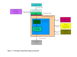
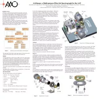
A view of the assembled spectrograph is shown in Figure 2. The base for construction is a 2400 x 1500mm optical table. The detector controller electronics boxes which sit on top of their cameras are not shown. The construction is modular for ease of assembly, alignment and maintenance. The modules are: the slit exchange mechanism, collimator module, two dispersers (including mounts and rotators), and two cameras and the two camera articulation assemblies. Slits and slit exchange mechanism MOS slits are assembled from a 40 slitlets, each containing ten fibers,which are located on chords of the nominal slit arc. (The IFU slit contains 32 slitlets of sixteen fibres.) A field lens is contacted with the fibre ends using optical grease. The slits are removable from the spectrograph with their fibres attached. The slit exchange mechanism is based on a wheel with four stations, on for each of the two MOS slits, one IFU slit and one illuminated calibration slit. These slits are rather loosely attached to the wheel. When a slit is in the observation position in the collimator it is clamped via a set of kinematic mounts to accurately position it. A single blade type system shutter may be deployed in front of the observing slit. Back-illumination of the MOS fibers is required so the 2dF positioner may see the fiber buttons at the field plate. The two MOS slits, which each correspond to one of the 2dF field plates, are mounted at 180° from one another so they may be serviced by a common back-illumination unit. This unit incorporates a clamshell that engages with the slit at the back-illumination position and closes over it to prevent stray light escaping into the spectrograph. LEDs are used with a ‘bent’ cylindrical condenser lens to illuminate the slit. The IFU slit does not require back-illumination. • INTRODUCTION • AAOmega is a dual beam bench-mounted spectrograph to replace the two existing 2dF spectrographs which are mounted on the top end ring of the Anglo-Australian Telescope. The 2dF fiber positioner will be retained and new multi-object spectroscopy (MOS) fibers will be run from 2dF to the spectrograph which will be located in the Coudé West focus room. These new fibers will be 38 metres long (compared with the original 7.5 metre 2dF fibres). • The existing SPIRAL 512 fibre IFU, at Cassegrain focus will also feed the AAOmega spectrograph. This will replace some of the functionality of the recently decommissioned RGO Spectrograph. The existing SPIRAL slit will be replaced to fit AAOmega slitlets. The full optical and mechanical system is shown in Figure 1, below. AAOmega: a Multi-purpose Fiber-fed Spectrograph for the AATGreg Smith1 (gas@aaoepp.aao.gov.au), Will Saunders1 Terry Bridges2, Vladimir Churilov1, Allan Lankshear1, Peter Gillingham1, Roger Haynes1, John Dawson1, David Correll1, Lew Waller1, Roger Haynes1, Gabriella Frost11. Anglo-Australian Observatory. 2. Department of Physics, Queen's University, Kingston, Ontario. . Collimator The double beam Schmidt collimator is an open frame construction. It incorporates a mirror, a dichroic beamsplitter and two corrector plates, on for the red beam and one for the blue. The correctors differ only in the design wavelengths for their anti-reflection coatings. The mirror is 500mm in diameter but only a vertical strip 190mm wide is illuminated by the slit so the non-working portion of the mirror surface is masked to suppress stray light. Hartmann shutters for spectrograph focusing are mounted immediately in front of the mirror. All optical components are mounted in ‘billboard’ style mounts. Dispersers A VPH grating is located in each beam. A full suite of gratings is provided for the spectrograph, to cover low dispersion (R~1500), medium dispersion (R~3500) and high dispersion (R~8000). These are manually exchangeable and each grating holder is encoded so the grating in place may be identified by software. (Gratings will not be exchanged during night.) To facilitate this each grating is mounted in its own housing which incorporates kinematic seats. Grating holders are masked to suppress stray light which falls outside the beam footprint. Gratings are mounted on DC motor driven rotary tables which incorporate incremental encoders so grating angle may be changed by the spectrograph control system in the course of the night. Cameras The red and blue F/1.3 Schmidt cameras are similar: they incorporate identical (except for coatings) mirrors and and correctors but the curvature of the field flattening lenses and the spacing of the optics differ slightly. See Figure 3. Figure 2 General view of AAOmega spectrograph Detectors are cooled using liquid nitrogen, so the cameras are evacuated. The 250mm diameter corrector plates are doublets and function as vacuum vessel windows. To resist air pressure loads the doublet must act as a composite structure so cementing of the doublet elements is critical. A mechanism is included to allow adjustment of axial focus and tip and tilt of the detectors with their field flattener lenses. This design is based on one used in the 2dF spectrograph spectrograph cameras wherein a stiff ring carrying the detector assembly via vanes is attached to a thin flex ring at two points. The flex ring is attached to the camera structure at two points at 90° to the previous points. Three motorised, encoded micrometer actuators are attached to the stiff ring and the combination of the strokes of these determines the translation and tip and tilt of the ring. See Figure 4. Camera Articulation Camera articulation is provided by Newport RV350 HAHLT rotation stages, which incorporate an incremental encoder into a geared DC motor driven worm drive. The overhanging moment load that would otherwise be imposed on the rotary stages is relieved using recirculating ball bearing carriages on curved rails under the rear of the camera.. Environment The Coudé West room exhibits temperature stability of order 0.1°C over four hours. To assist in maintaining this level of stability it is intended to restrict access to the room to daytime only. Beneath the room is a large concrete block mounted on air bags for vibration isolation. The AAOmega spectrograph will be mounted on this using legs passing through clearance holes in the floor. Figure 1 AAOmega optical and mechanical system diagram The opportunity will be taken to make improvements to the positioner and to replace the old Quantex guide camera with a more modern one. • FIBERS • AAOmega MOS fibers will be Polymicro FBP 140 168 198 ( replacing 2dF’s ‘wet’ FVP fibers). The better red transmission allows us to use the 38 meter length required to implement a bench-mounted spectrograph. A circuitous route, down the Serrurier truss and through the Coudé optical tunnel in the horseshoe has been found, between the top end and the Coudé West room. This involves much fiber handling when 2dF is removed and installed at instrument changes as the MOS fiber bundles will remain attached to the 2dF top end when it is removed from the telescope. • The number of guide fibre bundles on each field plate will be doubled to eight per plate. • The SPIRAL IFU uses FVP fibers and we accept that these (~18 metres long) will have virtually no throughput at 950 nm. • SPECTROGRAPH • The main system parameters for the spectrograph are: • MOS Slits Two 145mm long, 392 fibres/slit • IFU Slit 145 mm long, 512 fibres • Collimator F/3.15 dual beam Schmidt • Beamsplitter Dichroic, 570nm cut • Gratings VPH • Pupil 190mm diameter • Cameras F/1.3 Schmidt • Detectors 2048 pixels spectral x 4098 pixels spatial, 15 um pixels • Each camera and its E2V CCD44-82 detector are optimised for their wavelength range. • Blue camera – 370 to 580nm Red camera - 560 to 950nm Figure 4 Detector focus mechanism – exploded view Figure 3 Exploded view of camera