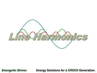
Line Harmonics
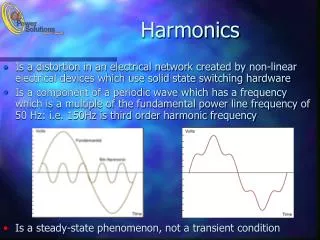
Line Harmonics. What are “Harmonics”?. Any waveform can be broken down into a sum of sine wave components that are multiples(harmonics) of the main “fundamental” frequency. 1st (fundamental) harmonic. 3rd harmonic. 5th harmonic. Harmonic Frequency 1 60 Hz

Line Harmonics
E N D
Presentation Transcript
What are “Harmonics”? • Any waveform can be broken down into a sum of sine wave components that are multiples(harmonics) of the main “fundamental” frequency. 1st (fundamental) harmonic 3rd harmonic 5th harmonic Harmonic Frequency 1 60 Hz 3 180 Hz 5 300 Hz • Harmonic orders are an “infinite series” • As harmonic orders increase, they typically diminish in magnitude. • Usually, orders above the 13th harmonic are negligible in power systems.
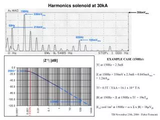
Harmonic Spectrum for a 6-pulse drive Typical AC drive Harmonic Spectrum – Lower harmonic orders have higher magnitudes – Magnitudes decline as the harmonic order increases
What causes Harmonic Distortion? • Any “non-linear” load * • AC and DC drives. • Large power supplies with rectifiers, as in UPS systems. • Electronic ballasts for fluorescent lighting. • Small power supplies on office equipment, PCs, copiers * “Non-linear loads” are any loads that are not 100% resistive, inductive, or capacitive. Solid-state switches (SCRs, IGBTs, & diodes) pull power unevenly from the AC line. “Linear loads” include incandescent lighting, resistive heaters, induction motors running across the line, etc.
Effects of Harmonic Distortion • Overheating of distribution system components • Improper operation of equipment on same power feed • Mandatory oversizing of transformers, wiring & switchgear • Resonances with power factor correction capacitor banks • Shortened equipment life
Rectifier configurations & harmonic order Bridge type harmonics* 2-pulse 3,5,7,9, … (single phase) 6-pulse 5,7,11,13,17,19… ( 3 phase) 12-pulse 11,13,23,25,…. ( 3 phase) 18-pulse 17,19,35,37,…. ( 3 phase) * Harmonic order = nP ± 1 ( ‘P’ = no. of pulses, ’n’ an is integer) SINGLE PHASE DRIVE 3 PHASE DRIVE 6-pulse input 3 PHASE DRIVE 12-pulse input
How AC Drives cause Harmonic Distortion Rectifier DC Filter Each diode conducts only a few degrees at the peak of each cycle, keeping capacitor voltage topped off. TO INVERTER LOAD 460 VAC 650 VDC 3 phase line voltage (Diode Conduction time) 650 VDC Bus
AC Drive Current and Voltage Distortion I phase Line Current RMS Current Peak current can be over 2 x rms VF-F Line Voltage (phase-to-phase) RMS Voltage Voltage appears clipped or “flat-topped”
Harmonic Standard: IEEE 519 • IEEE 519 is a standard that sets limits for both current and voltage distortion. • IEEE 519 is widely misunderstood and misapplied in the industry • Glossary • IL load current of the equipment (drive system) • ISC short circuit capability of the circuit • PCC point of common coupling • THD total harmonic distortion • DEMAND FACTOR drive load expressed as a % of circuit capability
VOLTAGE DISTORTION LIMITS • 5% THD maximum on circuits < 69 kV • not to exceed 3% distortion on individual harmonic • CURRENT DISTORTION LIMITS • Allowable distortion depends on the stiffness of the supply
THD = Demand Factor = (Load current)/(circuit capability) *100% Example: 100 amp drive on a 200 amp feed yields a D.F. of 50% Total Current THD = %THD/DF THD at drive = 45% 100 amp drive on a 500 amp supply, DF = 20% 5% transformer, Isc=500/0.05=10,000 amps; Isc/Iload=10,000/500=20 Need to meet 5% THD (current)
Harmonic Mitigation methods • Line reactor • Drive isolation transformer • Multi-pulse drives (12 and 18 pulse) • Passive harmonic filter • Active shunt (canceling) filter • Active front end drive
Add a Line Reactor XL = 2pfL TO INVERTER LOAD C L • Installing an input line reactor of 3-5% impedance will reduce harmonics and peak currents. • Reactors work to smooth line current by forming an L-C circuit with the capacitors, widening the conduction angle of each diode. • Adding a dedicated isolation transformer will have slightly better results, but at greater cost.
AC Drive Current and Voltage Distortion - with a reactor Without a reactor With a 3% line reactor I phase I phase Line Current RMS Current VF-F VF-F Line Voltage (phase-to-phase) RMS Voltage
100 75 50 25 0 6-pulse diode rectifier % Harmonic input current 1 5 7 11 13 17 19 Harmonic Order 6-pulse input drive configuration • Single point input power entry • Input line reactors reduce harmonic distortion • Single point motor connection • Integral output reactors The standard 3% input reactors provide adequate impedance so that a dedicated isolation transformer is not typically necessary. Input reactors reduce the impact of 5th and 7th harmonics on the distribution system 460V INPUT CURRENT TRANSFORMER (OPTIONAL) INPUT VOLTAGE Input Power
100 75 50 25 0 12-pulse diode rectifier INPUT CURRENT INPUT VOLTAGE % Harmonic input current 1 5 7 11 13 17 19 Harmonic Order 12-pulse input drive configuration • Low power line harmonic currents • Eliminates 5th and 7th harmonics • Improves power factor • Reduces KVA loading from line or generator power Installation requires an isolated input transformer with separate delta and wye secondary windings (30-degree phase shift). Taps for secondary voltages must be balanced to within 3% of each other. 460V (WYE) 460V (DELTA) Input Power
100 75 50 25 0 18-pulse diode rectifier INPUT CURRENT INPUT VOLTAGE % Harmonic input current 1 5 7 11 13 17 19 Harmonic Order 18-pulse input configuration • Low power line harmonic currents • Eliminates 5th,7th,11th & 13th harmonics • Improves power factor • Reduces KVA loading from line or • generator power Installation requires isolated input transformer with (3)20o phase shifted secondary windings.Taps for secondary voltages must be balanced to within 3% of each other. 460V 20O shift Input Power
Current distortion of Multi-pulse drives Without reactor With 5% reactor
Active Front End solution POWER FLOW 4Q Drive Active Bridge Inverter 3-phase line LCL Filter M The 4Q Drive eliminates typical AC drive harmonics keeping THD (total harmonic distortion) below 4%, well within IEEE519 guidelines Control • The INVERTER section is a standard (6) IGBT PWM (pulse width modulated) inverter • The ACTIVE BRIDGE rectifier is a (6) IGBT PWM bi-directional converter • The LCL FILTER is a low-pass design that removes high frequency harmonics • The CONTROL section provides signals to both bridges
100 75 50 25 0 % Harmonic input current 1 5 7 11 13 17 19 Harmonic Order AFE - for CleanPower Input current comparison Conventional diode rectifier AC Drive AFE AC Drive (with input reactor) 100 75 50 25 0 Active IGBT converter Diode rectifier % Harmonic input current 1 5 7 11 13 17 19 Harmonic Order Virtually no harmonic content is produced by the active front end, which evenly distributes conduction. High harmonic content is the result of short duration conduction of the diode rectifier.
0o Input voltage P.F. = cos(0o) = 1.0 True Unity Power Factor Drive The AFE ensures that input current is always in phase with voltage, regardless of motor speed and load. UNITY P.F. = • No PF correction needed • No PF utility penalties