Harmonics
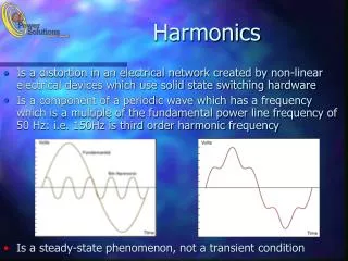
Harmonics. What are harmonics. It falls into the Power Quality category of Power Systems There are three main classes of PQ Under Voltages Over Voltages Waveform Distortions Harmonics belong to Waveform Distortion category. Remember we generate Sine Waves.

Harmonics
E N D
Presentation Transcript
What are harmonics • It falls into the Power Quality category of Power Systems • There are three main classes of PQ • Under Voltages • Over Voltages • Waveform Distortions • Harmonics belong to Waveform Distortion category.
Remember we generate Sine Waves • We don’t want waveforms that are not sine waves either current and/or especially voltage.
Three Classes of Voltage disturbances Voltage disturbances Under Voltage Over Voltage Waveform Distortion Impulsive Transient Oscillatory Transient Swells Harmonics A. Voltage B. Current Sags Notches Outages
So what is Harmonics • First a distorted waveform on the power system is a waveform that is not sinusoidal such as a square wave. • If that waveform is periodic i.e. it repeats itself every cycle it was shown by a man named Fourier that it can be made up by summing a fundamental sine wave with sine waves of integer number multiples of the frequency of the fundamental sine wave • These integer number multiples sine waves are called harmonics.
What causes Harmonics • Since we generate sine waves it is not the utility, but it is the load, which means it is the current that is distorted, this in turn can cause distortion to the voltage by the line impedance. • What cause the current to be distorted. A load that has a non linear impedance. • What is a non linear impedance, well let’s look a what is a linear impedance. Linear impedance that we know are resistance, inductance, and capacitance. • There may be a phase shift between current and voltage, but both current and voltage are sinusoidal.
Line Impedances Load Impedance
Let’s see how adding sine waves of different frequency causes waveform distortion Fundamental frequency A 3rd harmonic 3*fund frequency Distorted waveform Primary freq is that of fund.
Let’s take the same fundamental and add the same third harmonic but shifted 180 degrees. The waveform looks completely different. So what harmonic frequencies the waveform has, what amplitude the different harmonic frequencies are and what the phase shift of them is greatly affect the resultant waveform
Now let’s see how this non linear impedance causes waveform distortion.
We understand the idea behind harmonics but what I have is a distorted waveform how do I determine what harmonics can make that waveform • First we have to develop the general harmonic form for a distorted waveform 8 X(t)= a0 + (ancos n(2 f)t + bnsin n(2 f)t n=1 X(t) is the distorted waveform and now we have to figure out how to solve for a0, an, bn That is a lot of math so here is the answer T 2 1 a0 = X(t)dt T -T 2 T T 2 2 2 2 an = X(t) dt cos n(2 f)t bn = X(t) dt sin n(2 f)t T T -T -T 2 2
When you hand calculate the harmonics you usually do it so you end up with this expression, as it is what comes from the formulas. 8 X(t)= a0 + (ancos n(2 f)t + bnsin n(2 f)t n=1 But it can be expressed instead of cosine and sine terms as a cosine(or sine) term with a phase angle. This is the way you will see from meters. 8 X(t)= a0 + (cncos [n(2 f)t + On] n=1 bn cn= an2 +bn2 On =tan-1 an
Also many times it is easier to work with angles instead of time as really a sine function deals with angles in radians. We change time to an angle in our sine function by 2 f t = O or wt=O where w = 2 f and f= 1/T Remember T is one period or 2 and So d =dt So we can rewrite our formulas as: 2 f t = O T O 2 1 1 2 a0 = X(t)dt = X( )d O O T 2 -T 0 2 T 2 2 1 2 an = X(t) dt cos n(2 f)t = X( ) cos(n ) d O O O T -T 0 2 T 2 2 1 2 bn = X(t) dt sin n(2 f)t = X( ) sin (n ) d O O O T -T 0 2
Let’s work a problem We have already changed time into angles v 0 2 -v 1 2 1 2 a0 = X( )d O O = Vd O + -Vd O 2 2 0 0 1 = V -2 V + V =0 2 So the average value or DC component a0 =0 and looking at the waveform we can see that is correct
Solving for an v 1 2 an = X( ) cos(n ) d O O O 0 2 0 -v 1 2 an = V d cos(n ) O O + -V d cos(n ) O O 0 2 1 Vsin(n ) O Vsin(n ) O =0 = n 0 n
1 2 Solving for bn bn = X( ) sin (n ) d O O O 0 1 2 bn = V d sin(n ) O O + -V d sin(n ) O O 0 v 2 0 2 1 Vcos(n ) O Vcos(n ) O = + -v n 0 n = 1 for all n 2V V = 1 cos n = cos n + 1 + cos n2 cos n n n 2V 4V but 1 cos n = 0 for n=2,4,6,8,….. And n For n=1,3,5,7…. n
Putting it all together 0 8 0 X ( )= a0 + (ancos n(2 f)t + bnsin n(2 f)t O n=1 4V 1 1 1 X (O ) = sin + sin 3 + sin 5 + sin 7 +….. O O O O 3 5 7 v So this harmonic analysis is actually a good way to mathematically represent this waveform as there is really no way else to describe it in an equation form 0 2 -v Well let’s add up these harmonics and see if we get a square wave
I only added up to the seven harmonic and it is starting to resemble a square wave and I would actually get a square wave if I went to infinity If v=1 then 4V =1.273 . The other cool thing is if I can figure out how to get rid of the harmonic terms in a square wave I can get a sine wave 4V 1 1 1 X (O ) = sin + sin 3 + sin 5 + sin 7 +….. O O O O 3 5 7
2v Let’s see what happens when we shift the x axis 2 0 0 1 1 2 = 2V O = V a0 = 2Vd O + 0 d O 2 2 0 0 1 1 an 2Vsin(n ) O = 2V d cos(n ) O O = =0 0 n 0 1 2V 2V bn -cos(n ) O = 2V d sin(n ) O O = = -cos(n ) O +1 n 0 n 0 4V bn = For n=1,3,5,7,9,… For n=2,4,6,8,… bn =0 n 4V 1 1 1 sin + sin 3 + sin 5 + sin 7 +….. O O O O X (O ) = V+ 3 5 7
2 2 v Now let’s move the y axis into the center of the square wave 0 a0 -v = 0 No DC offset 3 2 3 1 2 bn 2 = V d sin(n ) O O + -V d sin(n ) O O - 2 2 3 2 1 2 Vcos(n ) O Vcos(n ) O = + n - n 2 2 cos(n ) cos(n ) 2 2 V 3 cos(n ) cos(n ) + cos(n ) + cos(n ) = 2 2 2 2 n 3 cos(n ) = cos(n ) = cos(n ) = 0 for all n 2 2 2
3 1 2 an 2 = V d cos(n ) O O + -V d cos(n ) O O - 2 2 3 2 1 2 V sin(n ) O -Vsin(n ) O = + n - n 2 2 -sin(n ) -sin(n ) 2 2 V 3 sin(n ) - sin(n ) sin(n ) + sin(n ) = 2 2 2 2 n 3 sin(n ) = sin(n ) -sin(n ) = 2 2 2 4V sin(n ) = 2 n 4V 1 1 1 X (O ) = cos - cos 3 + cos 5 - cos 7 +….. O O O O 3 5 7
Again this graft shows that the harmonic components are correct
Let’s work a real problem IR A half wave rectifier Current has harmonics VR Voltage here is still sinusoidal Graph of IR
Solve for Fourier coefficients 1 V V cos( ) O a0 = V sin d O O = = 2 2 0 0 Has DC For n=1 have to evaluate integral with this term = 0 1 V 1 an = Vsin d O cos(n ) O O = sin(n+1) - sin(n-1) d O O O 2 0 0 V -cos(n+1) cos(n-1) O O + an = n 2 n+1 n-1 0 0 1 0 Gotta watch this term as it will give us problems for n=1 -2V 2 3 V -cos(n+1) cos(n -1) 1 1 3 0 an = + + 2 n+1 n+1 n-1 n-1 -2V 4 For n=2,3,4… 15 V -cos(n+1) 1 5 0 an = + =0 2 n+1 n+1 -2V 6 For n=1 35
Solve for Fourier coefficients For n=1 have to evaluate integral with this term = 1 1 V 1 bn = Vsin d O sin(n ) O O = cos(n-1) - cos(n+1) d O O O 2 0 0 V -sin(n+1) sin(n-1) O O + = 2 n+1 n-1 0 0 Gotta watch this term as it will give us problems for n=1 bn n V -sin(n+1) sin(n -1) bn = + V 1 2 n+1 n-1 2 2 0 For n=2,3,4… V -sin(n+1) 3 0 V bn = + = 2 n+1 2 4 0 For n=1 5 0 6 0
V V I (O ) = + sin - cos 2 - cos 4 - cos 6 -….. 2V 2V O 2V O O O 2 3 15 35 We have DC, sin, cos, odd and even harmonics, hum!
Let’s look at this waveform - -5 7 11 6 6 6 6 5 6 6 OK why are we looking at this waveform, does it have any practical value if so what.
A diode Bridge This is a typical front end of a drive. You can see the waveform for one phase is like what we are going to analyze. A B C
V - -5 7 11 6 6 6 6 5 6 6 Let’s start, by now we should start to see that a0 =?, yes 0 11 5 1 6 6 V 5 11 + 7 a0 = = =0 Vd O + -Vd O 2 2 6 6 6 6 7 6 6 11 5 6 1 6 an V d cos(n ) O O + -V d cos(n ) O O = 7 6 6 11 5 6 6 1 Vsin(n ) O Vsin(n ) O = 7 n n 6 6
V 5 11 sin(n ) – sin(n ) – sin(n ) + sin(n ) 7 = 6 6 n 6 6 sin(n ) 5 sin(n ) 6 6 V 5 5 =0 = sin(n ) – sin(n ) – sin(n ) + sin(n ) n 6 6 6 6 an =0 11 5 6 1 6 bn V d sin(n ) O O + -V d sin(n ) O O = 7 6 6 11 5 6 6 1 Vcos(n ) O Vcos(n ) O = 7 n n 6 6
V 5 11 7 -cos(n ) + cos(n ) + cos(n ) - cos(n ) = 6 6 6 n 6 5 cos(n ) cos(n ) 6 6 V 5 -5 -cos(n ) + cos(n ) + cos(n ) - cos(n ) = 6 6 6 6 n V 5 -2cos(n ) +2cos(n ) = 6 6 n 0 but 5 cos(n ) = cos(n - n )= cos(n )cos(n ) + sin(n )sin(n ) 6 6 6 6 For n even, bn=0 2V bn cos(n ) 1-cos(n ) = 6 n
4V For n odd, bn = cos(n ) 6 n bn n 4V Notice no 3rd or 9th or 15 or odd multiples of 3s harmonics, that is a good thing 1 cos( ) = 1.102V 6 3 0 b1 5 5 b1 7 7 9 0 b1 11 11
So what have we seen so far • We generate a 60 hertz voltage sine wave • Waveform distortion is caused by the load having non linear impedance, therefore causing the current to be distorted • Constant cycle to cycle waveform distortion can be represented by integer number harmonics through Fourier Series • We have learned that this representation can lead well to filtering out harmonics to get back to a fundamental sine wave • We have learned the math behind the harmonic analysis Ick!!
Let’s talk about symmetry • As we were going over the harmonics we saw some had only sine terms some had only cosine terms. Some had both. • Some had only odd harmonics and some had both odd and even harmonics. • Is there any pattern? • Yes, we have three types of symmetry Even Odd ½ wave
Even Symmetry Odd Symmetry X(t)=X(-t) X(t)= -X(-t) cos(- ) = cos( ) O O sin(- )= - sin( ) O O Cosine wave has even symmetry Sine wave has odd symmetry Harmonics only have sine terms Harmonics only have cosine terms Has both sine and cosine terms as it does not have either odd or even symmetry Axis placement is everything
½ wave symmetry This ½ wave is the same This ½ wave is not the same as this As here Has both even and odd harmonics as it does not have ½ symmetry When you have ½ symmetry you only odd harmonics X(t)=-X(t+T/2)
What components do these waveforms have? (Sine, Cosine, both, Odd, both odd and even, DC) Sine, Cosine, Odd, Even DC, Sine, Odd DC, Cosine, Odd Sine, Odd, Even Sine, Cosine, Odd
So what does all this mean? • Y Axis placement will greatly simplify hand solution of harmonics by only having either sine or cosine terms if odd or even symmetry exists. But for meters you don’t get to choose the axis placement everything is usually referenced off of A phase voltage. So all other harmonics will have phase angles associated with them, but I don’t care to much as I am not calculating it, but I have to be aware of it. • If I know the device I am concerned about and realize this device should produce wave shapes with ½ wave symmetry and I see both even and odd harmonics I most likely have a problem with the device. • If I use a regular clamp on CT to measure current I am already eliminating DC from my picture. This may give me an incomplete picture so I must be aware of it.
Well we showed the harmonic component of a waveform but now we would like to plot them instead of in the time domain let’s use the frequency domain v 0 2 -v 4V 1 1 1 X (O ) = sin + sin 3 + sin 5 + sin 7 +….. O O O O 3 5 7 4V 1 1 1 X (O ) = Cos( - ) + cos(3 - )+ cos(5 - )+ cos(7 - ) O O O O 2 2 2 2 3 5 7 1 2 3 4 5 6 7 h 1 2 3 4 5 6 7 h Phase angle Magnitude
It is easy to see that for a period waveform the harmonics are discrete integers and what has to be removed to get back to a fundamental sine wave. But what happens to something that is not periodic. 4V 1 1 1 X (O ) = Cos( - ) + cos(3 - )+ cos(5 - )+ cos(7 - ) O O O O 2 2 2 2 3 5 7 1 2 3 4 5 6 7 h 1 2 3 4 5 6 7 h Phase angle Magnitude This would be something like a transient waveform. Now these waveforms create harmonics that are integer and non integer harmonics and there can be a lot of them. However, because it is a transient it is short lived and usually doesn’t cause a problem unless resonance is involved, such as voltage magnification we learned about in transients class. That means we don’t usually worry about harmonics associated with transients.
It would suit us well to learn however what the transient spectrum for a transient might look like. This is the job of the Fourier Transform • The Fourier Transform encompasses the Fourier series. Remember the Fourier Series used for calculating the harmonics for a periodic function. And that is discrete integer harmonics. But a transient waveform is not periodic and exist for only a short period of time. • Let’s look at a single square wave to illustrate.
(2) T V 2 8 -V F (W) = f(t) e-jwt dt = v e-jwt dt = e-jwT/2 -e jwT/2 jw -T 8 -T 2 ejx-e-jx =sin x 2 2j -V = 2V sin(wT/2) = 2V sin(wT/2) = e-jwT/2 -e jwT/2 jw *T/2 w WT/2 VTsin(x) x Which is a sinc function wT/2= wT/2= W=2 =2 f T For f = 60 w=377 or 1st harmonic
OK what does this mean? DC component Amplitude of some of the harmonics and there are infinite harmonics between each of them 1 3 2 0 8 X(t)= a0 + ( bnsin n(2 f)t n=1 The unit step function has infinitely many harmonics that are non integer, just so happens that the integer harmonics are zero for this function
Again transient conditions which produce all these non integer harmonics don’t last too long and are usually not a problem unless resonance exist so we won’t deal with them again!
Let’s look at the symmetrical component expressions of harmonics as to whether they are positive, negative, or zero sequence • Why is this important. Well it is a good way to determine whether a motor will vibrate more with different harmonics and whether neutrals will overload From Symmetrical Components B C C B A A A B C Zero Positive Negative
C The second Harmonic A A=Vcos2(wt)=Vcos2(wt) B=Vcos2(wt-120)=Vcos(2wt-240) =Vcos(2wt+120) C=Vcos2(wt+120)=Vcos(2wt+240)=Vcos(2wt-120) B Positive A=Vcos(wt) B=Vcos(wt-120) C=Vcos(wt+120) B A This is the fundamental C Negative So second harmonic is negative sequence. It rotates opposite in a motor than the positive