Comprehensive Guide to Compression Mould Design | Corporate Training & Planning
860 likes | 1.11k Views
Learn about advantages, limitations, and procedures of compression molding for thermosetting materials. Understand types of compression moulds and variable factors affecting the process. Get insights for corporate training and planning.

Comprehensive Guide to Compression Mould Design | Corporate Training & Planning
E N D
Presentation Transcript
COMPRESSION & TRANSFER MOULD DESIGN CORORATE TRAINING AND PLANNING
TYPES OF THERMOSET PLASTICS • Phenole formaldehyde (PF) • Urea formaldehyde (UF) • Melamine formaldehyde (MF) • And others CORPORATE TRAINING AND PLANNING
Compression molding of the thermosetting materials has certain advantages as follows :- Waste of material in the form of sprue runners and transfer culls is avoided and there is no problem of gate erosion. . A maximum number of cavities can be used in a given mold base without regard to demands of a sprue and runner system. Compression molding is readily adaptable to automatic loading of material and automatic removal of molded articles. Automatic molding is widely used for small items such as wiring device parts and closures. In general, compression molds are usually less expensive to build than transfer or injection types. CORPORATE TRAINING AND PLANNING
Limitations of Compression Molding : In the case of very intricately designed articles containing undercuts, side draws and small holes, the compression method may not be practicable. Articles of 0.35 in thickness compression molding would be slower than transfer slights fins or "flash" are to be expected on molded articles where the mold sections meet. Articles of polyesters require very careful adherence to all rules for draft; they also require generous ejector areas to avoid fracture on release from the molds. In some cases, compression molding of thermosetting material may be unsatisfactory for production of articles having extremely close dimensional tolerances, especially in multiple cavity molds, particularly relation to non-uniformity of thickness at the parting line of the molded article. CORPORATE TRAINING AND PLANNING
Procedure for Compression Molding : The sequence of operations constituting the molding cycles is as follows :- Open the mold ; Eject the molded articles ; Place article in shrink or cooling fixtures when necessary to maintain close dimensional tolerances (if necessary) ; Remove all foreign matter and flash from the mold, usually by air blast Place inserts or other loose mold parts if any ; CORPORATE TRAINING AND PLANNING
Load molding compound (powder or performs, cold or preheated); • Close the heated mold (breathe if necessary); • For thermosetting materials, hold under heat and pressure until cure is completed. Certain materials require cooling under pressure for best control of the dimensions ; • For thermoplastic materials hold under pressure and cool to harden the articles. • The temperature of the mold and the pressure applied are extremely important and it is advisable to follow the recommendations of the manufacturer for each grade of material used. CORPORATE TRAINING AND PLANNING
There are five very important variables in the compression molding of thermosetting materials which determine the pressure required to produce the best molding in the shortest length of time. These are as follows :- 1. Design of the article to be produced : projected area and depth wall thickness obstruction to vertical flow (such as pins, louvers and sharp corners) 2. Speed of press in closing ; use of slow or fast acting self contained press use of fast acting press served by hydraulic line accumulator system capacity of accumulator to maintain constant follow up of pressure on material CORPORATE TRAINING AND PLANNING
3. Plasticity of material ; degree and type of preheating density of charge (perform or powder) position of charge in cavity mobility of resin under pressure type of filler (wood flour, cotton flock, macerated fabric, asbestos, glass or mica). 4. Over all temperature of mold ; temperature variations within cavity and force of mold 5. Surface condition of mold cavity and force ; highly polished chrome plated surface polished steel poor polish (chromium plating worn ; pits, gouges and nicks) Molding pressures required for most thermosetting materials follow the pattern established for phenolic materials. CORPORATE TRAINING AND PLANNING
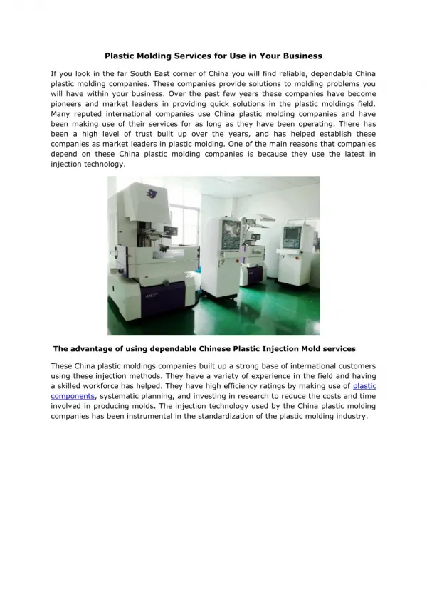
Compression Moulds Compression moulds are made of High Carbon high Chromium H11, H 13 Hot die Steels. It consists of a lower cavity or cavities also known as Bottom force,& core or Punch also called as an upper force . The molding portions of the molds are hardened and highly polished. The two halves of the mold are mounted between the platens of a hydraulic compression press. The weighted raw material or Charge is placed in the cavity of heated mould in Powder form or performs. Both the mould halves are closed by the press, the top force causes the Plastics material to flow in the mold. The material is compressed into the shape by the application of heat and pressure which causes a chemical reaction in the material .The material is chemically cross linked or set or cured into the shape of the required Product. CORPORATE TRAINING AND PLANNING
Types of Compression Moulds Hand Moulds Semi–automatic moulds Automatic moulds. For most economic production moulds are made from High grade HDS i.e, H 11,or H 13 steels which are hardened and polished. CORPORATE TRAINING AND PLANNING
Hand Compression Mould These moulds are used for smaller production runs or Prototypes, experimental jobs that require minimum mold cost & Parts having Open Tolerances. These moulds are used advantageously for complex Parts incorporating number of loose pull pins and wedges. A Hand Mold weights less than 10 Kgs for easy manual handling. As all the mould operations are manual, Automation is not possible. Hence Hand Moulds are slow in operation which requires longer cycle time and is labour intensive, adding to Production cost as compared to other type of moulds Moreover, the molds are more easily damaged by misalignment and mishandling etc which may result from Improper mould operation and closing of the mold. CORPORATE TRAINING AND PLANNING
1.Top force ret. Plate 2. Bottom force plate 3. Bottom force 4. Top force 5. Guide pillar 6. Guide bush 7. Bottom force insert CORPORATE TRAINING AND PLANNING
Semi-automatic Compression Mould Semi-automatic moulds are fastened in the press for the duration of the run. The press-operator automatically releases the mould piece as the press opens, thus permitting ready removal, semi-automatic moulds are used for mass production of jobs. While operating semi-automatic moulds the operator is required for only a brief period during each molding cycle. Almost all Parts with limited design complexities can be produced by semi-automatic compression molds. CORPORATE TRAINING AND PLANNING
Classification of Semi automatic Moulds. 1. Semi-automatic Open Flash Mould 2. Semi-automatic Fully Positive Mould 3. Semi-automatic Landed Positive Mould 4. Semi-automatic Semi Position Mould CORPORATE TRAINING AND PLANNING
HEAT SOURCE CORPORATE TRAINING AND PLANNING
Automatic Mould In principle Automatic Moulds are similar to semi-automatic moulds. They have additional mechanical features, which serve to perform all operations automatically in sequence, when used in an automatic press. The Plastics material is measured & charged in to the mould from a hopper by a automation device that are set in a motion by a master timer. The timer operates the valve or linkage device to close the press and open it again, when the molding cycle is completed. Mould opens & subsequently Ejector pins demoulds the molded piece from the mold cavity or core so that it may be picked or blown in to a receiving pile by external device. CORPORATE TRAINING AND PLANNING
Automatic moulds are used when automatic presses are available. These moulds are generally expensive than semi-automatic moulds but their operational cost is considerably low.Automatic Moulds eliminates human errors but there may be difficult to keep in adjustment for certain jobs & from maintenance standpoint. Automatic Moulds are best adopted for jobs requiring better accuracy , stringent Tolerances & for mass Production. 1. OPEN FLASH MOULD 2. LANDED PLUNGER MOULD 3. POSITIVE MOULD 4. SEMI POSITIVE MOULD CORPORATE TRAINING AND PLANNING
CALCULATION OF LOADING CHAMBER DEPTH D = VT – VC A Where, D – Depth of loading space from top of cavity to pinch-off land VC - Volume of actual cavity space (cm3) VT - Total volume of loose powder (cm3) A – Projected area of the loading chamber (cm2) Where, V – Total volume of part including flash factor Around 10 to 20%. This is the standard Practice adapted to calculate the depth of loading chamber . CORPORATE TRAINING AND PLANNING
DESIGN OF THE MOULD CAVITY Generally Moulds are designed ruggedly to withstand Thrusts, Pressures, loads, stress from mechanical standpoint, hence the mould cavity should have adequate dimensions to withstand the clamping pressure & also to prevent distortion within the specified tolerance limits of deformation. Cavity Strength Calculation CORPORATE TRAINING AND PLANNING
For Rectangle Cavity In the case of larger moulds the distortion tendency due to Internal pressure should be considerd & in case small distortion takes place, the effect is not determinant, where the moulds are built in sections & fitted into a bolster, then distortion at the core, of the open side may be found using the following formula. CORPORATE TRAINING AND PLANNING
FLASH THICKNESS ALLOWANCES Allowances for flash thickness in compression moulds, using thermosetting compounds are:- Rag-filled high impact compound - 0.25mm Cotton – flock compounds in large molds - 0.2mm Wood – flour compounds in small molds - 0.1mm All other moulds are for all other compounds allow 0.13mm (except as previously noted) Because of the flash thickness that we are considering in the mould design the depth of cavity become: Depth of Cavity = Minimum dimension of moulding + Shrinkage of compound The flash thickness adds to the total thickness of the part and this thickness must be subtracted from the basic cavity depth in order that the finished Part may have the desired wall thickness. CORPORATE TRAINING AND PLANNING
Technological Determination of the Number of Cavities OR Impressions in Compression Mold During calculation of the number of cavities or impressions by technological method for multi-cavity moulds, the following parameters should be considered. On the machine side we have to consider – available machine clamping force, and size of the platen. For the moulding materials we have to consider the compression pressure of the material and for the moulding the projected area should be taken into account during calculation. The calculation as follows: Claming force (kgf) = Projected area of the moulding (cm2) x Compression pressure of the plastic material kgf/cm2 CORPORATE TRAINING AND PLANNING
The projected area can vary depending on the size of the component as well as on the design of cavity or loading chamber and the compression pressure also can vary based on the type of plastics materials. For example, in a vertical flash or positive type of mold, there is no need of horizontal land. But in the case of horizontal flash type of mold the flash width should be taken in to account for the determination of the projected area. So the projected area in the case of vertical flash type is same as the projected area of the component. But, in the case of horizontal Flash type, 20% of the projected area of the component should be taken into account for the flash. Therefore, the actual projected area is - 1.2 x Projected Area of the component. CORPORATE TRAINING AND PLANNING
The compression pressure must be regulated in order to produce satisfactory parts economically. Pressure needed to mold a particular article depends on the flow characteristics of the material, the cavity depth and the projected are of the piece part. Generally it is recommended that minimum molding pressure of 240 kg/cm2 of projected area be used. However, in practice, about 300 kg/cm2 of projected area is used to compensate for any variables that may be encountered. After finding the clamping force required for one impression, the number of impressions can be determined from the actual clamping force available for a particular machine – i.e. No. of Impression = Clamping force available on the machine possible Clamping force required for an impression Using this Technical formula, the number of impressions can be determined. CORPORATE TRAINING AND PLANNING
Heat Treatment of mould parts • Hardening and Tempering • Dimensional & Shape stability • Surface treatment • Testing of mechanical properties • Stress relieve • Mould polishing CORPORATE TRAINING AND PLANNING
ADVANTAGES OF COMPRESSION MOULD OVER TRANSFER MOULD :- • Waste of material in the form of sprue runners and transfer culls is avoided and there is no problem of gate erosion. • Internal stress in the molded article is minimized by the shorter and multi directional flow of the material under pressure in the mold cavity. In the case of high impact types with reinforcing fibers, maximum impact strength is gained. This results because reinforcing fibers are not broken up as is the case when forced through runners and gates in injection molding. • A maximum number of cavities can be used in a given mold base without regard to demands of a sprue and runner system. CORPORATE TRAINING AND PLANNING
Compression molding is readily adaptable to automatic loading of material and automatic removal of molded articles. Automatic molding is widely used for small items such as wiring device parts and closures. • This technique is useful for thin wall parts that must not warp and must retain dimensions. Parts with wall thickness as thin 0.025 in are molded, however, a minimum wall thickness of 0.060 in is usually recommended. • For parts weighing more than 3 lb, compression molding is recommended since transfer or screw injection equipment would be very expensive for larger parts. • For high impact, fluffy materials, compression molding is normally recommended because of the difficulty in feeding the molding compound from a hopper to the press or performer. • In general, compression molds are usually less expensive to build than transfer or injection types. CORPORATE TRAINING AND PLANNING
Compression Mould Design Tips When designing a mould for the compression molded part, it is important to keep in mind that the goal is to produce quality parts in as short a cycle as possible with a minimum of scrap. To achieve these goals, you will need a mold that has a uniform mold temperature, and is properly vented MOULD HEATING SYSTEM:- A uniform mold temperature means that the temperature of each half of the mold is the same (within 3° C ) for all locations when the mold is heated by oil or steam. Molds that are heated with electric cartridge heaters can vary by as much as 6°C. A mold with a uniform temperature, will fill easier and produce parts with less warpage, improved dimensional stability and a uniform surface appearance. Achieving a uniform mold temperature is dependent on your method of mold heating. CORPORATE TRAINING AND PLANNING
HEAT REQUREMENTS & HEAT CAPACITY:- To determine the amount of wattage needed to heat a mold the use of the following formula might be helpful: 1 1/4 kilowatts for every 45kg (100 pounds )of mold steel. (Note this formula will normally allow the mold to be heated to molding temperature in 1 to 2 hours) This does not include the ejector housing in the weight for the mold but it does include the “A” & “B” plates and the support plates behind the “A” & “B” plates. CORPORATE TRAINING AND PLANNING
Locating a heater on the center line on the mold is not recommended, because the center of the mold is normally hot enough without any additional heat. Typically, the cartridge heaters are located in the support plates at a distance between heaters of 65mm. There should be a minimum of one thermocouple to control each half of the mold. In larger molds, it is recommended to have more than one thermocouple in each mold half. This will result in better control and more uniform mold temperatures. The thermocouples must be located in the “A” & “B” plates, between two heaters if possible & at a distance of 32mm to 38mm from the closest cartridge heater. This distance is to be measured from the edge of the thermal couple hole to the edge of the cartridge heater hole. CORPORATE TRAINING AND PLANNING
The distance from the thermal couple to the heater is important because a heater that is too close will cause the thermocouple hole to the edge of the cartridge heater hole. The distance from the thermal couple to the heater is important because a heater that is too close will cause the thermocouple to turn off the heat before the mold is at temperature. A heater that is too far away from the thermal couple will result in a mold that over heats and then gets too cool. Likewise, it is not a good practice to position a thermal couple so it senses the external surface temperature of the mold. If possible, it should be located 38mm to 51mm inside the mold, since the temperature taken there, is less susceptible to outside influences and therefore more stable. CORPORATE TRAINING AND PLANNING
TRANSFER MOULD DESIGN Transfer Molding material is used when the molding dimensions, shape or configuration, impose conditions which cannot be met by compression molding. Two of the main conditions imposed by the molded component which necessitate the use of the transfer molding method are: In case where the wall thickness & dimensions of the molding is critical and has to be held to a close tolerance. Where the shape of the molding necessitates the use of thin, weak sections of metal or thin small diameter pins, which could be damaged by the force created by the initial flow of material when using the compression method. CORPORATE TRAINING AND PLANNING
TRANSFER POT CALCULATIONS The dimensions of the pot, if it is round or square can be calculated once the area is known:- Total area of Pot Ap = Total projected area of cavities, runners and sprue + 25 – 30% of total projected area. Volume of Pot Vp = Total volume of all the piece parts, the runners and the sprue plus approximate volume of a small amount for a 0.5 to 1mm thick cull multiplied by Bulk factor of the compound. Depth of Pot = Vp Ap CORPORATE TRAINING AND PLANNING
CORPORATE TRAINING AND PLANNING CLOSED POSITION
CORPORATE TRAINING AND PLANNING RECOMMENDED DESIGN OF LOWER PLUNGER
FACTORS THAT INFLUENCE THERMOSET MOLDING Three important factors that must be considered in thermo set molding are: a) Temperature, b) Pressure, and c) Cure Time CORPORATE TRAINING AND PLANNING
TEMPERATURE Thermosetting Plastics materials must be heated to approximately 170 to 190C for optimum cure. Temperature for molding various materials can be determined by getting the information from the Material manufacturer. Higher temperature may degrade some of the physical properties , electrical characteristics & mechanical Properties of the material. Particularly in transfer molding, may cause the material precure before the cavity is completely filled. High temperatures may also cause blisters and burn Marks on the finished articles. Low Processing Temperatures will not allow the material to flow properly and result in incompletely cured parts with poor consistency, thus reducing the productivity of the cycle. CORPORATE TRAINING AND PLANNING