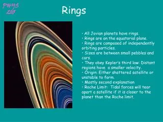
Rings
Rings. Compression and Oil Control Rings. Ring Locations. Top Ring Second Ring Oil Rings. Compression Ring Design. Compression rings must: Seal combustion pressure Aid the oil rings in controlling oil Transfer heat to the cylinder walls. Compression Ring Design. Materials Cast iron

Rings
E N D
Presentation Transcript
Rings Compression and Oil Control Rings
Ring Locations • Top Ring • Second Ring • Oil Rings
Compression Ring Design • Compression rings must: • Seal combustion pressure • Aid the oil rings in controlling oil • Transfer heat to the cylinder walls
Compression Ring Design • Materials • Cast iron • Ductile Iron
Ring End Gaps • Butt gap – most common • Lap joint – Childs & Alberts gapless ring • Bevel joint
Ring Actions • Scraping – on intake stroke rings scrape excess oil from the cylinder wall • Oil sealing – during the compression and exhaust events the rings ride on a film of oil (reduces friction and wear) • Gas loading – during the power event, the top ring is forced out against the cylinder wall by the cylinder pressure
Compression Ring Coatings • Chromium • Approx .0004” thick coating • Very hard and wear resistant • Takes longer to break in • Proper cylinder preparation very important
Compression Ring Coatings • Molybdenum (Moly) • .004” - .008” groove cut in ring face • Molten molybdenum is then sprayed into the groove • High melting point (Moly - 4750 F, cast iron – 2250 F, chromium – 3350 F) • Soft and porous • Retains oil • Combats scuffing • Short break in period
Oil Control Rings • Removes excess oil from the cylinder wall and returns it to the crankcase • The bottom rail scrapes oil directly into the crankcase • The top rail forces the oil through the oil drain back slots/holes in the piston and back into the crankcase
Ring Installation • Check: • Ring end gap • Use piston to square rind in bore approx 1 “ from the top and use feeler gauge to measure • Rule of thumb - .003” - .004” of gap for every inch of cylinder bore • If gap is too tight use a piston ring filer to widen gap • Ring side clearance – use feeler gauge
Ring Installation • Use a piston ring installer to avoid breaking rings, warping rings or scratching the piston