Download
1 / 32
350 likes | 1.34k Views
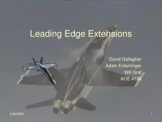
Design of a Composite Wing with Leading Edge Discontinuity. Daniel Hult AerE 423 Project December 12, 2009. Overview. Background Project Goals Design Computational Analysis Fabrication Testing Results & Conclusions Future Work. Background. Purpose

E N D
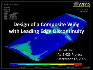
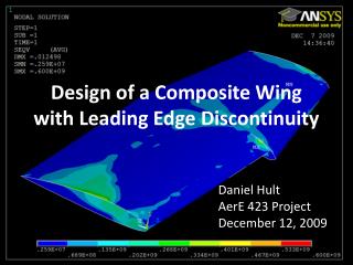
Design of a Composite Wing with Leading Edge Discontinuity Daniel Hult AerE 423 Project December 12, 2009
Overview • Background • Project Goals • Design • Computational Analysis • Fabrication • Testing • Results & Conclusions • Future Work
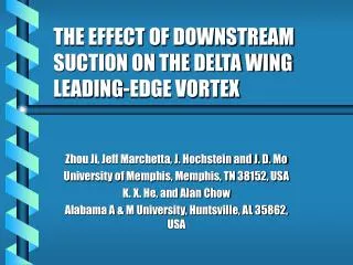
Background • Purpose • Discontinuity causes vortex to form, keeping flow attached to outer wing and ailerons • Improved stability and performance at high α • Spin prevention Cirrus Aircraft Company
Project Goals • Determine the structural feasibility of a composite, single-piece wing with a discontinuous leading edge. • Design, build and structurally test a single-piece composite wing.
Design • Phases: • Aerodynamic Analysis • Structural Design • Purpose of project is structural • Aerodynamics only to get accurate loads
Aerodynamics • XFLR5 Analysis • Open source aerodynamics for R/C gliders • Uses Vortex Lattice Method • Allows low Reynolds Number analysis of any wing
Structural Design • Laminate Study • Analysis of laminate geometry with comp_core • Varied combinations of 0/90 plies and ±45 plies • Loading • Tension and Bending • Compression and Bending • Laminates with more ±45 plies performed better in bending
Structural Design • Final Laminate • 6 plies of 0.002 in. thick bi-weave fiberglass • 4 plies at 0 and 90 degrees • 2 plies at +45 and -45 degrees
Computational Analysis • ANSYS used for Finite Element Analysis • Three cases tested • Isotropic material (aluminum) • Graphite-Epoxy composite • Fiberglass-Epoxy composite • 300 N distributed load at tip • Loading from XFLR5 • Depicted test to be performed
Computational Analysis • Fiberglass • Max Stress= 587 Mpa • Max disp = 1.25 cm
Fabrication • Mold • Airfoil sections cut out of particle board • Used as stencils to hotwire blue foam • 2 sections joined and handle added to root
Fabrication • Lay-up • Hand lay-up around mold • Wrapped and cured with vacuum assistance.
Testing • A Successful test would clearly accomplish project goals • Wing anchored at root with load applied at tip • Load added to tip until failure
Testing Screw Method Clamp Method
Testing • Wood mount failed along screws (20 lb) • Fiberglass failed along clamped shims (40 lb)
Results & Conclusions • Wing failed at clamped root at small load • ANSYS predicted stress concentrations and therefore failure at discontinuity • The results were inconclusive, necessitating further testing
Future Work • Better fabrication techniques and materials • Two-piece wing • Carbon Fiber • VARTM or Pre-Preg • Better testing and mounting methods • Metal or composite mounting plate and insert • Metal or composite tip insert for loading
References • Abbott, Ira H. and Albert E. von Doenhoff. Theory of Wing Sections: Including a Summary of Airfoil Data. New York: Dover Publications, Inc. c1959. • “CAPS™ and Stall/Spin.” Cirrus Aircraft Company. Accessed 12 October 2009. <http://www.whycirrus.com/engineering/stall-spin.aspx>. • Deperrois, André. “About XFLR5 calculations and experimental measurements” August 2008. <http://xflr5.sourceforge.net/xflr5.htm#_Help>. • Deperrois, André. “Guidelines for XFLR5 V4.16.” April 2009. <http://xflr5.sourceforge.net>. • Goyer, Robert. “Airplane on a Mission: Created for use in the humanitarian field, the Quest Kodiak delivers raw utility at a great price.” Flying Magazine. February 2009 <http://www.flyingmag.com/turbine/1344/quest-kodiak-airplane-on-a-mission.htmlQuest Kodiak>. • “Kodiak Features.” Quest Aircraft Company. Accessed 29 September 2009. http://www.questaircraft.com/index.php?filename=features.php • Meschia, Francesco. “Model analysis with XFLR5.” RC Soaring Digest. February 2008: p27-51. • NASA Langley Research Center. “Spin Resistance” Updated 17 October 2003. <http://oea.larc.nasa.gov/PAIS/Concept2Reality/spin_resistance.html>.
Acknowledgments • Dr. Vinay Dayal, Professor • Chunbai Wang & Peter Hodgell, TA’s • AerE 462 group, especially Robert Grandin for ideas and support • Iowa State University, Department of Aerospace Engineering
Background Airliners.net • Uses • Messerschmitt Bf-109 • Large commercial jets • NASA Spin Prevention Tests • Cirrus SR20 • Quest Kodiak Airliners.net Cirrus Airliners.net
NASA Spin Prevention Figures from NASA Langley report
Aerodynamics • Airfoil Design • NACA 2412 chosen for basis • Common, well-known low-speed airfoil • Discontinuity created by extending NACA 2412
Aerodynamics • Wing Design • Basic wing designed to be fabricated and tested structurally • NACA 2412 inner section (0.3 m) • Modified airfoil outer section (0.2 m) • b/2=0.5 m • cr=0.25 m
Table A1: Test Laminates Laminate Study
Computational Analysis • Isotropic • Max Stress= 654 Mpa • Max disp = 1.34 cm
Computational Analysis • Carbon Fiber • Max Stress= 600 Mpa • Max disp = 1.25 cm