Download
1 / 16
160 likes | 255 Views
Explore groundbreaking RF technologies to enhance accelerator performance and efficiency. Discover advancements in SRF thin films, high-gradient NC cavities, RF photocathodes, and more. Collaborative research aims to revolutionize electron beam generation and transport while reducing energy consumption. Dive deep into the development of next-gen RF photocathodes, novel superconducting materials, and efficient NC structures. Join us in unlocking the potential of innovative RF solutions for future linear accelerators!

E N D
RF R&D Perspectives in EUCARD-2 Peter McIntosh (STFC Daresbury Laboratory)
WP12Innovative RF Technologies Reducing the footprint, machine energy consumption and overall cost of linear accelerators are of primary importance for all accelerators being developed today. Big Wins! • This JRA focuses on the development of a range of technical solutions that has the potential to achieve significant performance increases in gradient, efficiencyand beam quality of RF-based accelerator systems. • Several novel techniques in the field of normal and superconducting RF technologyhave been selected, presenting the highest impact potential and with the additional benefit of profiting from exchanges and communication between these two distinct communities. • Main R&D areas encompass: • SRF Thin Films – C Antoine (CEA Saclay); • High Gradient NC Cavities – W Wuensch (CERN) • SRF HOM Beam Diagnostics – R Jones (Manchester University) • RF Photocathodes – R Nietubyc (NCBJ)
WP12 Collaborative Team SRF Thin Films High Gradient NC SRF HOM Beam Diagnostic RF Photocathodes
Fundamental Objectives RF Photocathodes Development of next generation advanced RF photocathodes, exploring revolutionary production techniques as lead deposition, diamond amplifier cathode and metallic photocathodes, enhancing the ability to reach fs response time, for more effective electron beam generation, capture and transport with high brightness and low intrinsic emittance. SRF Thin Films Exploitation of new superconducting materials, such as Nb3Sn and the development of new nano and multi-layer thin films, each anticipated to break new ground in the performance of SC accelerator cavities, with the potential of achieving gradients well beyond present Nbtechnology. High Gradient NC Cavities Development of an efficient NC structure capable of high gradient operation (Eacc > 100 MV/m) but free from dangerous wakefieldcontributions. SRF HOM Beam Diagnostics Development of electronics for utilising Higher Order Mode (HOM) signals from accelerating cavities for precision beam position diagnostics in high-energy electron linear accelerators, with the goal of improving beam quality and stability.
Pb Photocathodes Pbsurfaceprocessingoptimisation to reduce a dark current and improve QE • Pb layer treatment with EUV radiation: • λ = 10 – 70 nm, 5 ns pulses, rep. 10 Hz • energy density/pulse ≈ 30 mJ/cm2 • penetration depth ≈ 15 nm • Pb layer treatment with pulsed ion beams from IBIS Rod Plasma Injector: • Pb/Nbfilms of thickness 1 – 20 μm • treated with 1 μsAr ion pulses of 1 – 6 J/cm2 • Melting and recrystallization • Utilisation of standard photocathode/plug. • Standard ex-situ structural and morphological studies with SEM, XRF and XRD • Integrated stand for heat treatment, EUV irradiation and in-situ XRF-base purity and thickness diagnostics, QE and DC measurements • Measurements of resonance quality vsEacc for electron gun with pure and Pb-coated plug. • Pb/Nbphotocathode tests in HZDR SRF gun: • QE, lifetime, FE, DC and thermal emittance Micro-droplets removal
Diamond Amplified Cathode Generation of high average currents (>100 mA) well above what is currently achievable with high QE multi-alkali photocathodes (Smedley et al BNL). DAC is a very promising solution! Steps towards DAC at SRF gun: Physics and engineering design of a suitable cathode cell which contains the DAC. Laboratory tests of beam properties. Qualification of DAC in SRF gun at ELBE/HZDR and BERLinPro/HZB Challenges: Operation of DAC inside an SRF gun Beam properties (thermal emittance, response time) Field emission
Metal Photocathodes • Metal PC materials (e.g. Ag, Cu, Mg, Nb, Pb, Zr) characterisation and evaluate surface preparation procedures. • ESCALABII and Multi-probe surface analysis: • Compositional and chemical analysis • Surface roughness evaluation • Work function measurement • Quantum efficiency measurements • Transverse Energy Spread Spectrometer (TESS) for: • Transverse emittancemeasurements • QE measurements • Cathode transfer system to allow rapid evaluation of candidate materials and procedures in the VELA test facility. • Improve cathode QE and reduce emittance, providing high brightness beams for future FEL applications.
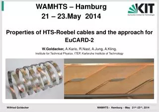
SRF Thin Films Multi-layer SRF Thin Film Fundamental Goal! Bulk Nb • Niobium on copper (µm): • After ~20 years stagnation • New revolutionary deposition techniques developed: • HIPIMS, CVD, ALD • Great expectations in cost reduction • Improved performances c.f. bulk Nb • Higher Tc material (µm): • Based on superheating model. • Higher field and Qoexpected • Higher Tc material (nm), multilayer: • Trapped vortex model (Gurevich) • Higher field and Qo expected • ~200 x Hc1 predicted • Specific characterization tools needed. • Better understanding of SRF physics needed. See C. Antoine (CEA) talk this afternoon
Thin Film R&D • CERN: • HIPIMS: Energetic deposition => better film microstructure (bulk-like, high RRR) • Nb3Sn: Development of a thermal deposition set up. • INP Grenoble: • Superconducting heterostructure deposition – CVD & ALD techniques. • ALD utilised to develop multilayer NbN/insulator/NbNcoatings. • CEA Saclay: • Optimisation of multi-layers. • Thin layers (d~) have higher HC1 • Measure HC1 using magnetometry. • HZB-Berlin: • Build an optimised RF testing resonator. • Rsvs B characterisation. • Investigate samples under external magnetic fields. HoBiCaT
CLIC Damped Detuned Structure (DDS) wakefield suppression: Strong detuning to provide moderate damping. Incorporation of damping manifolds, interleaving neighbouring cell modes. Assess perturbation sources (frequency errors, misalignment…) by means of combined RF (GdfidL) and beam dynamics (PLACET) simulations. Fabricate and test a prototype damped DDS structure. Wakefield Monitor: Develop wide-band (2 GHz) front-end electronics for CLIC and SwissFEL. Optimize signal/noise to reach theoretical µm-scale resolution. Allow for spectral analysis to extract information about higher order misalignments (pitch, roll, bend), whilst also giving simple ‘operator’ signal. Evaluating classical RF style option versus Electro-Optical approach with promising properties with respect to radiation damage, electromagnetic interference and bandwidth. Wakefield Management
X-Band RF Power Source Pulse compressor RF Source 10 MW some ms 1 kHz 20 MW – 200 ns 12 GHz 40 MW 200 ns 20 MW – 200 ns RF Source 10 MW some ms 1 kHz To the structure Pulse compressor • Develop affordableand reliabletechnical design for RF testing of CLIC X-band accelerating structures: • Modest power klystron used in ‘cluster’ configuration. • Pulse compressor optimisation. • Prototype and testing of sub-components.
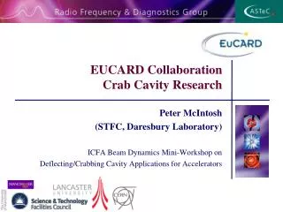
CLIC Crab Cavity System To complete the design, evaluation and high gradient testing of a CLIC crab cavity. Complete the testing of the cavities developed pre-EUCARD2 and the development of a new ‘fully-damped’ cavity solution. To understand and measure long-term phase stability in high power RF distribution and use this to develop an appropriate distribution scheme for the CLIC crab cavity system.
HOM Beam Diagnostic HOM-based beam diagnosticsfor XFEL: • Reduced emittance dilution from transverse wakefields. • Direct, on-line measurement of beam phase wrt RF phase. • Align beam on cavity axis. • Measure beam position intrinsically. • Measure cavity alignment within cryo-module. HOMBPM-electronics built for 1.3 GHz cavities in FLASH (SLAC, DESY): • Use 1 dipole mode at 1.7 GHz. • Used as operator tool for beam alignment. • Used for measurement of cavity alignment. • Demonstrated use as BPM: • 10 mm rmsresolution. • Difficulty: • Instability of calibration into BPM-signals (phase or frequency drifts?).
3.9 GHz System R&D • HOMBPM-Electronics for 3.9 GHz cavities in FLASH (EuCARD): • Due to higher frequency and 4-cavity coupling, use bands of modes instead of single modes: • Coupling modes around 5.4 GHz for high resolution • Trapped modes around 9 GHz for localized measurement • ~20 µm rms positional resolution achieved • 3.9 GHz cavities in the European XFEL vs. FLASH: • Significantly more challenging (8 coupled cavities c.f. 4) and higher frequency (4.5 MHz beam repetition rate c.f. 1 MHz) • Demands extensive theoretical and experimental studies
Infrastructure Benefits • SRF Photocathodes: • HZDR - ELBE • HZB - Hobicat– BerlinPro • VELA • SRF Thin Films: • Materials analysis infrastructure at CEA, HZB and INPG • Sputtering facility at CERN • High Gradient NC: • SwissFEL • CTF3 • HP test benches at CERN, CEA and Uppsala Univ. • SRF HOM Diagnostics: • FLASH and XFEL
Conclusions:Pushing the Envelope Integrated and balanced programme encompassing high performance capabilities across both SC and NC technologies. • Beam Generation: • New photocathodes providing demonstration of highest beam intensities and smallest beam emittances. • Acceleration: • Demonstration of the highest level of acceleration performance. • Beam Diagnostics/Control: • Demonstration of high performance and low cost beam position diagnostic.