Download
1 / 32
330 likes | 566 Views
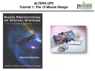
ALTERA UP2 Tutorial 1: The 15 Minute Design. ALTERA UP2 Tutorial 1: The 15 Minute Design. Figure 1.1 The Altera UP 1 CPLD development board. ALTERA UP2 Tutorial 1: The 15 Minute Design. Design. Compilation. Simulation. Verifcation. Graphical Entry. Timing Diagram. Program CPLD.

E N D
ALTERA UP2Tutorial 1: The 15 Minute Design Figure 1.1 The Altera UP 1 CPLD development board.
ALTERA UP2Tutorial 1: The 15 Minute Design Design Compilation Simulation Verifcation GraphicalEntry Timing Diagram Program CPLD Compiler Timing Analysis UP 1 Development Board HDLEntry Figure 1.2 Design process for schematic or VHDL entry.
Figure 2.3 MAX and FLEX seven-segment LED display segment names.
Table 2.4 UP 2 Board 10K20RC240 FLEX CHIP I/O pin assignments.
Figure 3.3 Using a PLA to implement a Sum of Products equation.
Figure 3.4 Examples of FPLDs and advanced high pin count package types.
ALTERA MAX 7000 Architecture Figure 3.5 MAX 7000 macrocell.
ALTERA MAX 7000 Architecture Figure 3.6 MAX 7000 CPLD architecture.
Figure 3.7 FLEX 10K100 FPLD die photo, PIA interconnects are visible.
Figure 3.9 Using a lookup table (LUT) to model a gate network.
XILINX 4000 Architecture – A LU Table FPGA Figure 3.12 Silicon wafer containing XC4010E 10,000 gate FPGAs.
XILINX 4000 Architecture – A LU Table FPGA Figure 3.13 Single XC4010E FPGA die showing 20 by 20 array of logic elements and interconnect.
Figure 3.14 Xilinx 4000 Family Configurable Logic Block (CLB).
Figure 3.15 CAD tool design flow for Field Programmable Logic Devices (FPLDs).
Chapter 4: Tutorial II Figure 4.1 The tutor2.gdf schematic.
. Figure 4.5 Enlarged view of tutor2 design showing bus connections.
Figure 4.6 Timing analysis using Registered Performance option.
Figure 4.7 Oscilloscope display of pushbutton switch contact bounce.