Download
1 / 6
60 likes | 74 Views
B PS S tatus R eport S UMMARY OF T AU C OMPENSATION T EST. Test performed at CERN AB-BI/PI Labs during the 30 th week.

E N D
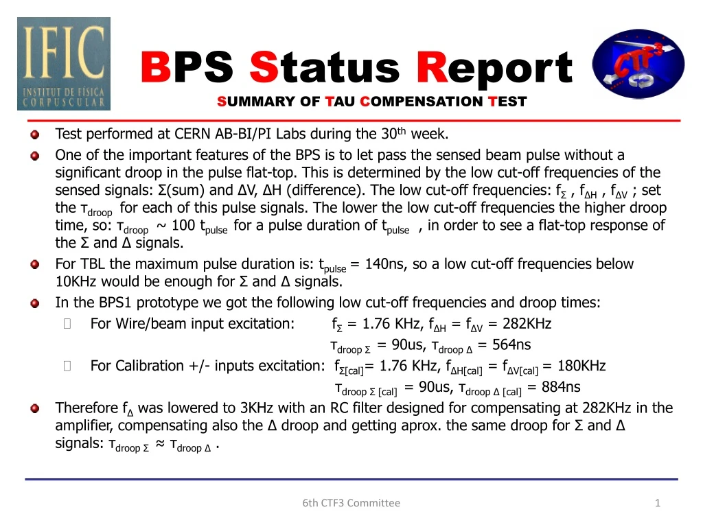
BPS Status Report SUMMARY OF TAU COMPENSATION TEST • Test performed at CERN AB-BI/PI Labs during the 30th week. • One of the important features of the BPS is to let pass the sensed beam pulse without a significant droop in the pulse flat-top. This is determined by the low cut-off frequencies of the sensed signals: Σ(sum) and ΔV, ΔH (difference). The low cut-off frequencies: fΣ , fΔH , fΔV ; set the τdroop for each of this pulse signals. The lower the low cut-off frequencies the higher droop time, so: τdroop ~ 100 tpulse for a pulse duration of tpulse , in order to see a flat-top response of the Σ and Δ signals. • For TBL the maximum pulse duration is: tpulse = 140ns, so a low cut-off frequencies below 10KHz would be enough for Σ and Δ signals. • In the BPS1 prototype we got the following low cut-off frequencies and droop times: • For Wire/beam input excitation: fΣ = 1.76 KHz, fΔH = fΔV = 282KHz • τdroop Σ = 90us, τdroop Δ = 564ns • For Calibration +/- inputs excitation: fΣ[cal]= 1.76 KHz, fΔH[cal] = fΔV[cal] = 180KHz • τdroop Σ [cal]= 90us, τdroop Δ [cal] = 884ns • Therefore fΔ was lowered to 3KHz with an RC filter designed for compensating at 282KHz in the amplifier, compensating also the Δ droop and getting aprox. the same droop for Σ and Δ signals: τdroop Σ ≈ τdroop Δ . 6th CTF3 Committee
BPS Status Report SUMMARY OF TAU COMPENSATION TEST • The compensation was good for the wire/beam-Δ signal, fΔ, but we faced a problem of different low cut-off freq, fΔ[calin], for calibration-Δ signal (100KHz of diff.). In the amplifier we can compensate exactly only for one cut-off frequency: fΔ= 282KHz, and we got overcompensation (a pulse raise instead of a droop) for calibration calibration-Δ signal. • After several tests and modifications in the RC filter of the amplifier and the BPS1 to make the cut-off freqs. Equal and then could compensate both correctly, the difference between them was kept constant (100KHz). • Therefore a compromise solution was taken to improve the first tau compensation made only for the wire/beam-Δ signal, fΔ = 282KHz: • For having better tau response only with the BPS1, both low cut-off freqs were low down to: fΔ = 170KHz (wire/beam) and fΔ[cal]= 70KHz (calibration); changing the some resistor values in the BPS1 PCBs. • We set the compensation frequency in the amplifier equal as the lower Δ cut-off frequency that it’s the Δ-calibration low cut-off frequency, fΔ[calin]. • This was the best compromise solution since we obtain flat pulse transmission, like Σ signal, for the time windows of interest in both cases: • Wire/beam input excitation: flat pulse transmission until 200ns [see PLOTS in slide-3]; • Calibration inputs excitation: flat pulse transmission until 2000ns [see PLOTS in slide-4]. 6th CTF3 Committee
SUMMARY OF TAU COMPENSATION TEST BPS-1 Wire at +6mm V,H Excitation Naked BPS-1 Pulse response ΔV, ΔH without tdroop by Amplifier (ΔV, ΔH signals compared with Σ pulse) BPS-1+AMPLIFIER Pulse response ΔV, ΔH with tdroop by Amplifier (ΔV, ΔH signals compared with Σ pulse) 6th CTF3 Committee
SUMMARY OF TAU COMPENSATION TEST BPS-1 Calibration + (V+,H+) Excitation Naked BPS-1 Pulse response ΔV, ΔH without tdroop by Amplifier (ΔV, ΔH signals compared with Σ pulse) BPS-1+AMPLIFIER Pulse response ΔV, ΔH with tdroop by Amplifier (ΔV, ΔH signals compared with Σ pulse) 6th CTF3 Committee
BPS Status Report SUMMARY OF TAU COMPENSATION TEST • As a result of the changes in the PCB, all BPS1 characterization measurements were repeated. • With BPS2 at IFIC, we are searching for the cause of Δ-calibration and Δ-wire/beam low cut-off frequency difference, in order to have the best pulse transmission performance, which is making: fΔ[cal] ≈ fΔ, and compensate them with the amplifier. This will ensure two things: • Flat-response until 2000ns for both, Δ-calibration and Δ-wire/beam, like Σsignal. • τdroop Σ ≈ τdroop Δ , which means the same pulse response for all signals beyond 2000ns. 6th CTF3 Committee
BPS Status Report Wire test and High Frequency testbenches construction [IFIC, week 39] Software development for the new wire-test setup [IFIC, week 42] (automatization of the BPS series measurements) Startup of 15 BPS series construction with its 30 PCBs and mechanical supports [depends on the tendering process, IFIC, week --] Assembling of BPSs and PCBs mounting [IFIC, week --] Calibration and characterization measurements of the BPS series with new wire test and HF setup [IFIC, week --] Delivery of BPS series and supports to be installed in TBL [IFIC, week --] 6th CTF3 Committee