Download

1 / 34
350 likes | 564 Views
PART 2 ELECTRORHEOLOGICAL SUSPENSIONS. ELECTRORHEOLOGICAL SUSPENSIONS. SUMMARY Review of electrorheological suspensions (ERS) Classification of ERS Mechanisms of the ER effect proposed by several researchers potential applications modelling. ELECTROACTIVE MATERIALS.

E N D
ELECTRORHEOLOGICAL SUSPENSIONS • SUMMARY • Review of electrorheological suspensions (ERS) • Classification of ERS • Mechanisms of the ER effect proposed by several researchers • potential applications • modelling
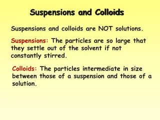
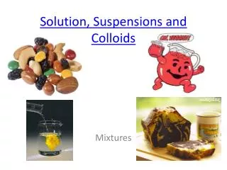
ELECTROACTIVE MATERIALS • An electro-active material is a suspension where a semiconductive material (particulate or liquid) is dispersed in a dielectric liquid medium. • The rheological properties change in reversible form by several orders of magnitude under external electric fields.
ELECTROACTIVE MATERIALS • Since the rheological properties can be easily controlled within a wide range, many scientific and technological applications may be developed. T. Hao , Adv. Colloid Interface Sci. 1-35, 97 (2002) H. Block, J.P. Kelley, J. Phys. D, 1661, 21(1988) A. P. Gast, C. F.Zukoski,Adv. Colloid Interface Sci.153,30(1989) T.C. Halsey Science 761,23(1992)
POTENTIAL APLICATIONS • Clutch, brake and damping systems, actuators, fuel injections systems • Joints and hands of robotic arms • photonic crystals. • Microswitches. • Mechanical-electronic interfaces C. F.Zukoski, Annu.Rev.Matter.Sci.23(1993)45 T.C. Halsey Science 23(1992) 761
Schematic illustration of structure change of ERS Before an external electric field is applied Structure of an electrorheological material after an electric field is applied
ERF Phenomena E With Electric field (E) DC ó AC Without Electric Field + - Increase in Viscosity
Continue experimental 4. Estructural arrangement observations
CRITICAL PARAMETERS • Electric Field Strength, E • two effects in competition for explain the changes in the yield stress, y, after applying the electric field • Frequency of Electric Field, • DC is mostly used to generate detectable ER effect • AC is used to study the ER mechanisms • ER effect is function of through and • Particle Conductivity, • determines J and it peaks yat o
CRITICAL PARAMETERS • Particle Dielectric Property, • the polarization depends on . • the electric double layer overlap is the reason • the dielectric constant changes with electrolytes • Particle Volume Fraction, • y and depend on , and exhibit a maximum • Percolation theory was used to understand this phenomenon
CRITICAL PARAMETERS • Temperature • Changes the polarizability of ERF because changes and . • Impact particle thermal motion • Liquid medium • sedimentation, viscosity, conductivity and permitivity of liquid causes pronounced differences for the ER effect. • Water content
FORCES RELEVANT TO THE ER EFFECT • After ER fluid is submitted to an electric field the particles should be polarized and appears a electrostatic force. However hydrodynamic, Brownian, van der Waals, DLVO and other forces act too. • Dimensionless groups that describe the relative importance of those forces. Eg. • Mason, Mn = 6/(0smE2) • Peclet, Pe = 6sma2/kT
PHASE TRANSITION • As increase the ERS changes from a disordered state to coexistence with a crystalline phase • Laser diffraction method and confocal scanning laser microscopy were employed to determine the crystal structure within fibrilated columns
POLARZATION PROCESS • Four kinds of polarization exist • electronic • atomic • Debye • Interfacial • The dielectric constant is = E + A + D + I
Rheological properties Results Viscosity vs shear rate a b
Continue results Shear stress vs shear rate a b
Model of ER suspensions . Bingham model t = ty + hplastic g – [h]fm Krieger-Dougherty hplastic = h0 [1- f/fm] . – [h]fm t = ty + h0 g [1- f/fm] J. W. Goodwin et.al. J Phys. Chem. B, 1997, 101, 1961-1967 L. Rejon. PhD Thesis, 1998, UNAM.
Kinetic chain model. [ Martin, J.E.; Odinek, J. J. Rheol. 1995, 39, 995]. • The kinetics of aggregation and fragmentation follows a phenomenological expression • The aggregation process is induced by the dipolar forces and hence the kinetic constant k is given by maximum stable size of the chains N(t)max,
This model predicts a viscosity proportional to the electric field squared and to inverse shear rate according to • is the volume fraction of particles
A rheological kinetic model for electrorheological suspensions
For weak electric fields and low shear rates, the viscosity grows slowly as a function of time with rate proportional to E*E. Under strong electric fields, the viscosity growth with time is exponential, and at long times the viscosity approaches the limit • At short times and in the case where , the model gives the proportionality of the characteristic time for structure formation with the viscosity and electric field, i.e.,.
Strong flow limit • Initially, the reference viscosity is the zero shear-rate viscosity. Asymptotic analysis of the model shows that at long times, for weak electric fields, the viscosity decreases with a rate proportional to • 1/( ) • whereas under strong electric fields, the viscosity is proportional to • In the latter case, the ratio of the electric field to the shear rate controls the viscosity decrease with time.
Conductivity contributions to the electrorheological effect.
Influence of electric field strength on ER response • Red =0.03 • Black =0.16 Silicon 100 DOP TCP • There are two effects in competition
Influence of fraction of particles on ER response • Black E=0.5 • Red E=1.0 • Green E=1.5 • Blue E=2.0 Silicon 100 DOP TCP