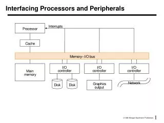
Interfacing Processor and Peripherals
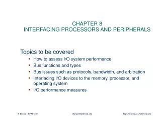
Interfacing Processor and Peripherals. Overview. Introduction. I/O often viewed as second class to processor design Processor research is cleaner System performance given in terms of processor Courses often ignore peripherals Writing device drivers is not fun

Interfacing Processor and Peripherals
E N D
Presentation Transcript
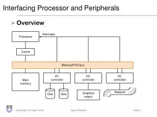
Interfacing Processor and Peripherals • Overview
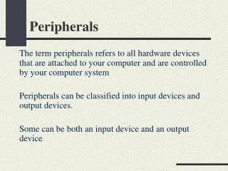
Introduction • I/O often viewed as second class to processor design • Processor research is cleaner • System performance given in terms of processor • Courses often ignore peripherals • Writing device drivers is not fun • This is crazy - a computer with no I/O is pointless
Peripheral design • As with processors, characteristics of I/O driven by technology advances • E.g. properties of disk drives affect how they should be connected to the processor • PCs and super computers now share the same architectures, so I/O can make all the difference • Different requirements from processors • Performance • Expandability • Resilience
Peripheral performance • Harder to measure than for the processor • Device characteristics • Latency / Throughput • Connection between system and device • Memory hierarchy • Operating System • Assume 100 secs to execute a benchmark • 90 secs CPU and 10 secs I/O • If processors get 50% faster per year for the next 5 years, what is the impact?
Relative performance • CPU time + IO time = total time (% of IO time) • Year 0: 90 + 10 = 100 (10%) • Year 1: 60 + 10 = 70 (14%) • : • Year 5: 12 + 10 = 22 (45%) • !
IO bandwidth • Measured in 2 ways depending on application • How much data can we move through the system in a given time • Important for supercomputers with large amounts of data for, say, weather prediction • How many IO operations can we do in a given time • ATM is small amount of data but need to be handled rapidly • So comparison is hard. Generally • Response time lowered by handling early • Throughput increased by handling multiple requests together
I/O Performance Measures • I/O bandwidth (throughput) – amount of information that can be input (output) and communicated across an interconnect (e.g., a bus) to the processor/memory (I/O device) per unit time • How much data can we move through the system in a certain time? • How many I/O operations can we do per unit time? • I/O response time (latency) – the total elapsed time to accomplish an input or output operation • An especially important metric in real-time systems • Many applications require both high throughput and short response times
I/O System Performance • Designing an I/O system to meet a set of bandwidth and/or latency constraints means Finding the weakest link in the I/O system – the component that constrains the design • The processor and memory system • The underlying interconnection (e.g., bus) • The I/O controllers • The I/O devices themselves (Re)configuring the weakest link to meet the bandwidth and/or latency requirements Determining requirements for the rest of the components and (re)configuring them to support this latency and/or bandwidth
I/O System Performance Example Instr execution rate 3 x 10⁹ -------------------------- = ------------------------ = 10,000 I/Os/sec Instr per I/O (200 + 100) x 103 Bus bandwidth 1000 x 106 ---------------------- = ----------------- = 15,625 I/O’s/sec Bytes per I/O 64 x 103 • A disk workload consisting of 64KB reads and writes where the user program executes 200,000 instructions per disk I/O operation and • a processor that sustains 3 billion instr/s and averages 100,000 OS instructions to handle an I/O operation The maximum I/O rate of the processor is • a memory-I/O bus that sustains a transfer rate of 1000 MB/s Each I/O reads/writes 64 KB so the maximum I/O rate of the bus is
Input and Output Devices 8 orders of magnitude range • I/O devices are incredibly diverse with respect to • Behavior – input, output or storage • Partner – human or machine • Data rate – the peak rate at which data can be transferred between the I/O device and the main memory or processor
Mouse • Communicates with • Pulses from LED • Increment / decrement counters • Mice have at least 1 button • Need click and hold • Movement is smooth, slower than processor • Polling • No submarining • Software configuration
Hard disk • Rotating rigid platters with magnetic surfaces • Data read/written via head on armature • Think record player • Storage is non-volatile • Surface divided into tracks • Several thousand concentric circles • Track divided in sectors • 128 or so sectors per track
Access time • Three parts • Perform a seek to position arm over correct track • Wait until desired sector passes under head. Called rotational latency or delay • Transfer time to read information off disk • Usually a sector at a time at 2~4 Mb / sec • Control is handled by a disk controller, which can add its own delays.
Calculating time • Seek time: • Measure max and divide by two • More formally: (sum of all possible seeks)/number of possible seeks • Latency time: • Average of complete spin • 0.5 rotations / spin speed (3600~5400 rpm) • 0.5/ 3600 / 60 • 0.00083 secs • 8.3 ms
Comparison • Currently, 7.25 Gb (7,424,000) per inch squared
More faking • Disk drive hides internal optimisations from external world
Disk Latency & Bandwidth Milestones • Disk latency is one average seek time plus the rotational latency. Disk bandwidth is the peak transfer time of formatted data from the media (not from the cache). • In the time that the disk bandwidthdoubles the latency improves by a factor of only 1.2 to 1.4
Media Bandwidth/Latency Demands • Bandwidth requirements • High quality video • Digital data = (30 frames/s) × (640 x 480 pixels) × (24-b color/pixel) = 221 Mb/s (27.625 MB/s) • High quality audio • Digital data = (44,100 audio samples/s) × (16-b audio samples) × (2 audio channels for stereo) = 1.4 Mb/s (0.175 MB/s) • Compression reduces the bandwidth requirements considerably • Latency issues • How sensitive is your eye (ear) to variations in video (audio) rates? • How can you ensure a constant rate of delivery? • How important is synchronizing the audio and video streams? • 15 to 20 ms early to 30 to 40 ms late tolerable
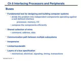
Buses: Connecting I/O devices • Interfacing subsystems in a computer system is commonly done with a bus: “a shared communication link, which uses one set of wires to connect multiple sub-systems”
Why a bus? • Main benefits: • Versatility: new devices easily added • Low cost: reusing a single set of wires many ways • Problems: • Creates a bottleneck • Tries to be all things to all subsystems • Comprised of • Control lines: signal requests, acknowledgements and to show what type of information is on the • Data lines:data, destination / source address
Controlling a bus • As the bus is shared, need a protocol to manage usage • Bus transaction consists of • Sending the address • Sending / receiving the data • Note than in buses, we talk about what the bus does to memory • During a read, a bus will ‘receive’ data
Types of Bus • Processor-memory bus • Short and high speed • Matched to memory system (usually Proprietary) • I/O buses • Lengthy, • Connected to a wide range of devices • Usually connected to the processor using 1 or 3 • Backplane bus • Processors, memory and devices on single bus • Has to balance proc-memory with I/O-memory • Usually requires extra logic to do this
Synchronous and Asynchronous buses • Synchronous bus has a clock attached to the control lines and a fixed protocol for communicating that is relative to the pulse • Advantages • Easy to implement (CC1 read, CC5 return value) • Requires little logic (FSM to specify) • Disadvantages • All devices must run at same rate • If fast, cannot be long due to clock skew • Most proc-mem buses are clocked
Asynchronous buses • No clock, so it can accommodate a variety of devices (no clock = no skew) • Needs a handshaking protocol to coordinate different devices • Agreed steps to progress through by sender and receiver • Harder to implement - needs more control lines
Increasing bus bandwidth • Key factors • Data bus width: Wider = fewer cycles for transfer • Separate vs Multiplexed, data and address lines • Separating allows transfer in one bus cycle • Block transfer: Transfer multiple blocks of data in consecutive cycles without resending addresses and control signals etc.
Obtaining bus access • Need one, or more, bus masters to prevent chaos • Processor is always a bus master as it needs to access memory • Memory is always a slave • Simplest system as a single master (CPU) • Problems • Every transfer needs CPU time • As peripherals become smarter, this is a waste of time • But, multiple masters can cause problems
Bus Arbitration • Deciding which master gets to go next • Master issues ‘bus request’ and awaits ‘granted’ • Two key properties • Bus priority (highest first) • Bus fairness (even the lowest get a go, eventually) • Arbitration is an overhead, so good to reduce it • Dedicated lines, grant lines, release lines etc.
Different arbitration schemes • Daisy chain: Bus grant line runs through devices from highest to lowest • Very simple, but cannot guarantee fairness
Centralised Arbitration • Centralised, parallel: All devices have separate connections to the bus arbiter • This is how the PCI backplane bus works (found in most PCs) • Can guarantee fairness • Arbiter can become congested
Distributed • Distributed arbitration by self selection: • Each device contains information about relative importance • A device places its ID on the bus when it wants access • If there is a conflict, the lower priority devices back down • Requires separate lines and complex devices • Used on the Macintosh II series (NuBus)
Collision detection • Distributed arbitration by collision detection: • Basically ethernet • Everyone tries to grab the bus at once • If there is a ‘collision’ everyone backs off a random amount of time
Bus standards • To ensure machine expansion and peripheral re-use, there are various standard buses • IBM PC-AT bus (de-facto standard) • SCSI (needs controller) • PCI (Started as Intel, now IEEE) • Ethernet • Bus bandwidth depends on size of transfer and memory speed
Example: The Pentium 4’s Buses Memory Controller Hub (“Northbridge”) DDR SDRAM Main Memory I/O Controller Hub (“Southbridge”) System Bus (“Front Side Bus”): 64b x 800 MHz (6.4GB/s), 533 MHz, 400 MHz Graphics output: 2.0 GB/s Gbit ethernet: 0.266 GB/s Hub Bus: 8b x 266 MHz 2 serial ATAs: 150 MB/s PCI: 32b x 33 MHz 2 parallel ATA: 100 MB/s 8 USBs: 60 MB/s
Buses in Transition • Companies are transitioning from synchronous, parallel, wide buses to asynchronous narrow buses • Reflection on wires and clock skew makes it difficult to (synchronously) use 16 to 64 parallel wires running at a high clock rate (e.g., ~400 MHz) so companies are transitioning to buses with a few one-way, asynchronous wires running at a very high clock rate (~2 GHz)
ATA Cable Sizes • Serial ATA cables (red) are much thinner than parallel ATA cables (green)
Giving commands to I/O devices • Processor must be able to address a device • Memory mapping: portions of memory are allocated to a device (Base address on a PC) • Different addresses in the space mean different things • Could be a read, write or device status address • Special instructions: Machine code for specific devices • Not a good idea generally
Communicating with the Processor • Polling • Process of periodically checking the status bits to see if it is time for the next I/O operation • Simplest way for device to communicate (via a shared status register • Mouse • Wasteful of processor time
Interrupts • Notify processor when a device needs attention (IRQ lines on a PC) • Just like exceptions, except for • Interrupt is asynchronous with program execution • Control unit only checks I/O interrupt at the start of each instruction execution • Need further information, such as the identity of the device that caused the interrupt and its priority • Remember the Cause Register?
Interrupt-Driven I/O • With I/O interrupts • Need a way to identify the device generating the interrupt • Can have different urgencies (so may need to be prioritized) • Advantages of using interrupts • Relieves the processor from having to continuously poll for an I/O event; user program progress is only suspended during the actual transfer of I/O data to/from user memory space • Disadvantage – special hardware is needed to • Cause an interrupt (I/O device) and detect an interrupt and save the necessary information to resume normal processing after servicing the interrupt (processor)
Interrupt-Driven Input add sub and or beq 2.1 save state 2.2 jump to interrupt service routine lbu sb ... jr 2.4 return to user code 1. input interrupt Processor user program Receiver Memory 2.3 service interrupt Keyboard input interrupt service routine memory