Download
1 / 27
270 likes | 407 Views
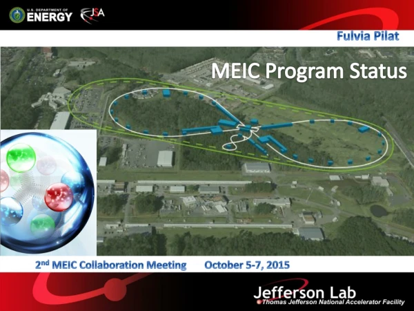
Fulvia Pilat. MEIC Program Status. Click to add title. Click to add subtitle. 2 nd MEIC Collaboration Meeting October 5-7, 2015. Outline. Recall baseline Program Update since last Collaboration Meeting ( March 2105) Plans for: Design, R&D, Engineering (FY16-17)

E N D
Fulvia Pilat MEIC Program Status Click to add title Click to add subtitle 2nd MEIC Collaboration Meeting October 5-7, 2015
Outline • Recall baseline • Program Update since last Collaboration Meeting (March 2105) • Plans for: Design, R&D, Engineering (FY16-17) • Selected design and R&D topics At the Collaboration Meeting: Collect Further input and feedback to plans Discussion of priorities • Plan and Expectations for the next 6 months (talk) After the Collaboration Meeting • Establish and communicate priorities for R&D funding • Plan Pre-Conceptual Design Report
Design Strategy: High Luminosity and polarization KEK-B already reached above2x1034/cm2/s All rings are figure-8 critical advantages for both ion and electron beam polarization • Spin precessions in the left & right parts of the ring are exactly cancelled • Net spin precession (spin tune) is zero, thus energy independent • Spin is easily controlled and stabilized by small solenoids or other compact spin rotators • Beam Design • High repetition rate • Low bunch charge • Short bunch length • Small emittance • IR Design • Small β* • Crab crossing • Damping • Synchrotron radiation • Electron cooling The MEIC design concept for high luminosity is based on high bunch repetition rate CW colliding beams
MEIC Baseline Baseline for the cost estimate • Collider ring circumference:~2200 m • Electron collider ring and lines : PEP-II magnets, RF (476 MHz) and vacuum chambers • Ion collider and booster ring: super-ferric magnets • SRF ion linac • Electron cooling: DC cooler and single-pass ERL, bunched-beam e-cooler Energy range • Electron: 3 to 10 GeV • Proton: 20 to 100 GeV • Lead ions: up to 40 GeV
Baseline Layout Warm Electron Collider Ring (3 to 10 GeV) Booster Linac Booster Ion Source Linac Ion Source CEBAF is a full energy injector. Only minor gun modification is needed MEIC Cost Review December 18 2014
Updates from last MEIC CM Last MEIC CM in March 2015, soon after the January EIC Cost Review Focus on: Baseline design optimization 100 MEV SRF linac option Racetrack vs. figure-8(Figure-8 for collider, studying racetrack option for booster) Emittance reduction in the e-ring Synchronization ERL Cooler design group started, cooling simulations Nonlinear Correction design group (SLAC/JLAB) Polarization: design updates and tracking Collective effects Beam formation R&D, External review of R&D for super-ferric program Internal reviews of: SRF R&D including crab cavity andEngineering MEIC related LDRD proposals Selected magnetized source R&D, e-cooling modeling, nuclear gluons with charm Engineering, ESH&Q, Civil Started engineering support activities (magnets, PEP-II…) Started soil evaluation study (funding from VA) Started study of radiation protection
MEIC Organization Hugh Montgomery Bob McKeown Cost Estimate Leigh Harwood Accelerators Fulvia Pilat Physics Rolf Ent Design Yuhong Zhang Facilities Rebecca Yasky R&D Fulvia Pilat Engineering Tim Michalski MEIC Organization established in July 2014 Funding: NP Accelerator R&D, JLAB re-direct, LDRD, SBIR, Commonwealth of Virginia S&T Review July 28-30, 2015
MEIC Design Plan Design activities are mostly based in CASA at JLAB Redirected resources to MEIC in 2015, effort level constant for FY2015-16 Acknowledge input from Mike Spata (CASA Director) and Yuhong Zhang (MEIC Design Leader)
MEIC Pre-project R&D plan • The MEIC pre-project R&D level is cost-effective , total <5M$ • Resources so far from NP EIC R&D funds, LDRD, SBIR • Anticipate increase of NP EIC R&D funds in FY16 after the LRP recommendation • (Meeting at NP November 12) • Request submitted to VA for 2.4 M$ in FY16-17 for MEIC Accelerator R&D
MEIC Engineering Plan • We initiated Engineering support work in FY15, and plan to ramp up in FY16-17 • Resources mostly internal redirect (12 GeV Project accelerator completed and overall • Project ramping down) • Acknowledge input from Tim Michalski (MEIC Engineering Leader)
Ion Injector: Short, Lower Energy/Cost Linac Talk M. Mustapha Proton KE: 285 130 MeV Lead ions: 100 42 MeV QWR/HWR cryomodules: 16 5 Total lengths: 110 55 m Total cost: ~factor 3 reduction
Step 2. Accumulating coasting beam BB cooler DC cooler Step 4/5. Cool and accelerate to 7.9GeV Step 7/8. Bucket-to-bucket transfer to the collider ring, repeat 9 (above) or 27 (below) times DC cooler Step 3. Capture to bucket BB cooler Step 6. Bunch compression Ion Injector: Smaller Racetrack Booster • Single booster option • Circumf.: 180 m • KE: 8 GeV • Polarization: good • Pol. Deuterons: yes Talk A. Kondratenko • Circumference: 120 m • KE: 3 GeV • Ion injection/formation scheme Talk M. Mustapha Talk J. Guo Hexagon Pre-booster
Talk F. Lin e-ring emittance 2nd sol. + decoupling quads 2nd sol. + decoupling quads 1st sol. + decoupling quads 1st sol. + decoupling quads Dipole set Dipole set Dipole set Dipole set New Baseline • The adoption of PEP-II lattice and magnets is cost effective but limits lumi performance because of large emittance . • Investigated several options to reduce emaittance • Optimizing the optics in a couple of sections • Adding (dipole) damping wigglers in the straight • Offsetting the beam in quads (~7 to 8 mm) • New magnets (instead of PEP-II magnets) but sill FODO cell arcs • Different types of arc cell, such as DBA, TME • She will show that “optimizing the optics in a couple of sections” already gives ~30% emittance reduction, at the cost of ~110m added length
Talk F. Lin e-ring spin tracking e- Magnetic field Polarization Spin tuning solenoid Spin Rotator IP • Spin tune scan for the electron beam at 5 GeV is performed based on a Monte-Carlo simulation. The result shows the polarization lifetime is about 8 hours at 5 GeV, and more important, a figure-8 shape MEIC collider ring has no synchrotron sideband resonances. • Continuous injection is not in the baseline design, but should be (re)considered to reach an even higher average polarization.
Beam Synchronization Talk V. Morozov x = 44 cm x = -50 cm Total bending angle and z length are fixed • Issue: energy-dependence of ion velocity desynchronizes ions with electrons • Explored various options without and in combination with harmonic jump • Moving ion orbit • Moving electron orbit and RF adjustment • Scanning synchronization • Considered engineering implications • Proposed baseline • Harmonic jump (to be demonstrated in simulations) • Adjusting electron path length using a movable chicane • Conclusions • Moving magnets is feasible: 10-15 shifts by a 3-person crew • Frequency adjustment is within tuning range
Nonlinear Dynamics: Ion Ring IP talks by Y. Nosochkov, M.-H. Wang, G. Wei At p/p = 0.3% (- 40x , + 40x) (- 40y , + 40y) (- 8p/p , + 13p/p) • Explored multiple compensation schemes –Isextupoles pairs in the arcs • Compensate chromatic smear at the IP • Compensate residual linear chromaticity with additional sextupoles
Ion Polarization Talk A.Kondratenko no stabilization stabilization by 1 solenoid • Figure-8 design • Zero spin tune independent of energy: spin precession in one arc is cancelled in the other • Spin control and stabilization with small solenoids or other compact spin rotators • Spin tracking in progress • figure-8 with an error • 2 T 2 m control solenoids can stabilize proton and deuteron spins up to 100 GeV
Cooler specs and challenges Talk S. Bensen So…what’s so hard about that? • Have to run very high current • Must have energy recovery or cost is too high • Also need SRF cavities but this means no magnetic fields in the cavities. • The current varies with position in the micro-bunch so space charge forces vary and cannot be perfectly compensated. • Any realistic design must bend the beam with discreet magnet elements. • No micro-pulsed high current source has been demonstrated • Bunch is very long in the cooler solenoid. Energy 20-55 MeV Charge 420 pC Repetition rate 476 MHz rms Bunch length 70 psec rms emittance 30 mm-mrad rms Energy spread (uncorr.)* 3x10⁻⁴ Energy spread (p-p corr.)* <2x10⁻³ Solenoid field 2 T Solenoid length 30 m Injector Magnetized COOL 15, Sept. 28-Oct. 2, 2015
Architectures: Traditional ERL and Linac-2-Linac • No merger • Up and down are linked in the same way • as traditional ERL • Bend happens after the cooling solenoid • May need bends for bunch stretcher • Cavity phasing and positioning important Same-cell energy recovery Bends Possible R2F/F2R with space charge Dump energy COOL 15, Sept. 28-Oct. 2, 2015
Status of the Super-ferric Magnet R&D Talks P. McIntyre T. Michalski SF Dipole – With and Without Coil Supports JLab has contracted TAMU to develop a 1.2m superferric model dipole Deliverable 1 – Concept Design – COMPLETE Deliverable 2 – Prototype Cable-In-Conduit winding – In Process, due at the end of CY’15
Cabling techniques NbTi Rutherford cable NbTi Cable-in-Conduit Pros: Uses mature cable technology (LHC). Semi-rigid cable makes simpler end winding. Semi-rigid round cable can be precisely located. Cryogenics contained within cable. Cons: Ends tricky to support axial forces. Cable requires development and validation. Entire cold mass is a He vessel.
Source for Magnetized Cooling Talk R. Suleiman Proposal awarded 2016 LDRD
SRF R&D: e-ring RF design Talk R. Rimmer nominal Impedance limited Synchrotron power limited 1.2 MW Klystron PEP-II RF cavity 2 MVA HVPS PEP-II Cavities in the SLAC tunnel • Re-use proven PEP-II RF stations • 476 MHz HOM damped 1-cell cavities • 34 cavities available • 1.2 MW klystrons, 13 available • Including power supplies etc. • Current limited by synch. rad. power at high energy, impedance at low energy
SRF R&D: ion-ring RF design 952.6 MHz single cell 4-seater CM(~4.3m flange to flange) New HOM damped cavity concept • 952.6 MHz HOM damped 1-cell cavities, modular JLab type cryomodule • High frequency/high voltage for short bunch (re-bucket at energy) • Double repetition rate for future luminosity upgrade
Talks J. Delayen A. Castilla SRF R&D: Crab cavity Design by ODU (A. CastillaPh.D project) 952.6 MHz “RF dipole” like LHC Modest RF system (no beam loading) Must have good HOM damping Count for 1 IP in baseline Assume cryostat cost/cavity same as ion storage ring
MEIC Civil: site planning Talk R. Yasky cs10 cs9 4 cs11 cs8 cs12 cs7 12 cs6 cs14 3 cs13 cs15 cs5 14 5 13 11 cs4 15 cs16 1 cs3 cs2 cs1 9 2 cs17 10 8 7 cs18 cs24 6 cs19 cs23 et5 cs20 cs22 cs21 et4 et3 et1 et2
Conclusion The accelerator program is progressing well: Solid baseline and first pass cost estimate Plan for FY16-17 in place Ongoing baseline design improvements Critical R&D initiated Progress on critical issues: synchronization, beam stripping and formation, spin tracking, beam-beam and collective effects, cooler design and cooling simulations Started engineering, civil and ESH&Q activities I will discuss future plans and priorities in my closing talk