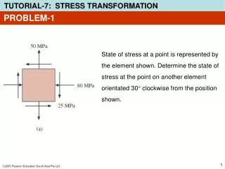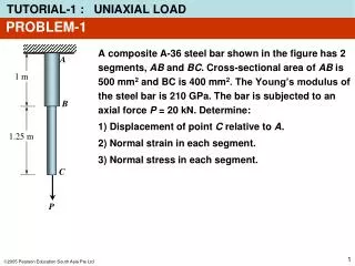

PROBLEM-1
E N D
Presentation Transcript
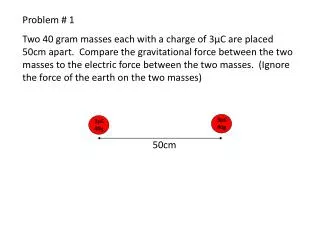
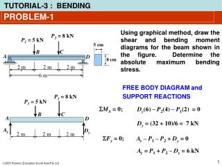
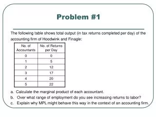
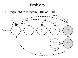
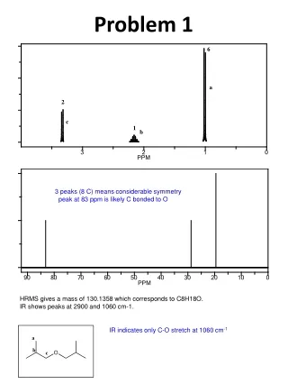
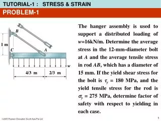
PROBLEM-1 The hanger assembly is used to support a distributed loading of w=16kN/m. Determine the average stress in the 12-mm-diameter bolt at A and the average tensile stress in rod AB, which has a diameter of 15 mm. If the yield shear stress for the bolt is ty = 180 MPa, and the yield tensile stress for the rod is sy = 275 MPa, determine factor of safety with respect to yielding in each case. B 1 m C A w 4/3 m 2/3 m
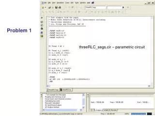
FAB + MC = 0 Cx a A C Cy 4/3 m 2/3 m We get FAB = 40 kN 1 m 1 m W Shear force: V = FAB/2 = 20 kN V V Shear stress: Bolt A FAB=40 kN PROBLEM-1 Equation of equilibrium (FABsina)(4/3) – W(1) = 0 a = tan-1(3/4) = 36.87o For bolt A t = 176.8 N/mm2
FAB C A PROBLEM-1 Factor of safety for bolt A: For rod AB = 226.4 N/mm2= 226.4 MPa Factor of safety for rod AB:
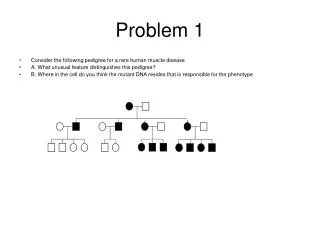
PROBLEM-2 Two bars are used to support a load P. When unloaded, AB is 125 mm long and AC is 200 mm long, and the ring at A has coordinates (0,0). If a load is applied to the ring at A, so that it moves it to the coordinate position (6.25 mm, -18.25 mm), determine the normal strain in each bar. B C 60o 200 mm 125 mm A P
D B C 60o 125 mm 200 mm A 230.67 mm C B y 108.25 mm x A’ 18.25 mm 62.5 mm 6.25 mm PROBLEM-2 Initial Geometry BD = ABcos60o = 62.5 mm AD = ABsin60o = 108.25 mm = 168.17 mm Final Geometry A’B = ?? = 143.975 mm = 205.47 mm
C B 143.975 – 125 125 A = A’ A’B – AB AB A’C – AC AC eAB = eAC = 205.47 – 200 200 = PROBLEM-2 Average normal strain = 0.1518 m/m = 0.0274 m/m
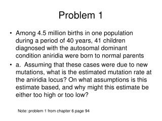
PROBLEM-3 The bar DBA is rigid and is originally held in the horizontal position. When the weight W is supported from D, it causes the end D to displace downward 0.5 mm. The wires are made of A-36 steel and have a cross-sectional area of 0.8 mm2, and Est= 210 GPa. Determine: • The normal strain & stress in wire BE. • The reaction force FBE and weight W. • The normal stress & strain in wire CD.
1 m 1.5 m D A B B’ D’ dB = 0.3 mm s = (210x109)(2x10⁻⁴) = 42x106 N/m2 PROBLEM-3 1) Normal strain & stress for wire BE: Displacement: DD’ = dD = 0.5 mm BB’ = dB Normal strain for wire BE: Applying Hook’s law for wire BE: s = E e
FBE 1 m 1.5 m D A B Dy Ay FBE = (42x106)(0.8x10⁻⁶) = 33.6 N Thus, Dy = 0.6FBE = 20.16 N PROBLEM-3 2) Reaction force FBE & weight W • Free-body diagram for the bar • Equations of equilibrium MA = 0; Applying uni-axial normal stress, where FBE is a tensile force:
Dy C W PROBLEM-3 The weight W FBD of point C: Equilibrium at point C: Fy = 0; W = Dy = 20.16 N 3) Normal stress and strain for wire CD Wire CD undergoes tensile force
PROBLEM-4 B The rigid pipe is supported by a pin at C and an A-36 steel guy wire AB. If the wire has a diameter of 5 mm, determine how much it stretches when a load of P = 1500 N acts on the pipe. The material remains elastic. E = 210 GPa. 2 m 60o A C “how much it stretches” What does it mean?? stretch = change in length =dAB
B P FBA)X P B FBA)Y FBA Cx Cx C C Cy Cy PROBLEM-4 B 2 m 60o A C Free-body diagram FBA)X = FBAcos 60o Component of FBA: FBA)Y = FBAsin 60o
FBA)X (2) – P(2) = 0 PROBLEM-4 Equations of equilibrium B FBA)X P MC = 0; FBA)Y FBA)X = P = 1500 N Cx C Applying uni-axial normal stress, Cy
FBA PROBLEM-4 Normal strain for wire BA: Change in length of wire BA: dAB = eBALBA = (7.27x10⁻⁴)(2000/sin60o) mm = 1.67 mm
PROBLEM-5 d A shear spring is made from two blocks of rubber, each having a height h, width b, and thickness a. The blocks are bonded to the three plates as shown. If the plates are rigid and the shear modulus of the rubber is G, determine the displacement of plate A if a vertical load P is applied to this plate. Assume that the displacement is small so that d = a tan g ag h a a
P P/2 g d V a b Rubber cross section PROBLEM-5 d h a a Free-body diagram after deformation Shear force: V = P/2 Displacement: Shear stress: d = a tan g a g Shear strain: