Understanding Unity Gain Configuration and Diode Behavior in Voltage Circuits
This article explains the behavior of unity gain configurations in circuits when connecting different voltage inputs, such as 2.5V to 5V. It highlights the impact of bulk capacitors at ground (GND) on preventing diode activation while ensuring the proper function of the configuration. It emphasizes the relationship between V-, Vout, and Vref, and describes the conditions under which the diode will turn on. Understanding these concepts can help in designing effective circuits without unintended diode activation.

Understanding Unity Gain Configuration and Diode Behavior in Voltage Circuits
E N D
Presentation Transcript
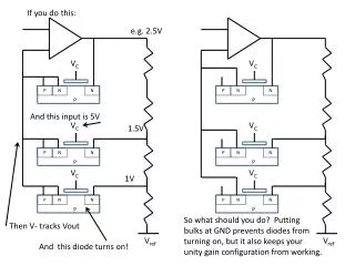
If you do this: e.g. 2.5V P P P P P P N N N N N N N N N N N N P P P P P P VC VC VC VC And this input is 5V VC 1.5V VC 1V So what should you do? Putting bulks at GND prevents diodes from turning on, but it also keeps your unity gain configuration from working. Then V- tracks Vout Vref Vref And this diode turns on!