DC Gun
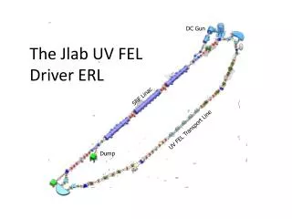
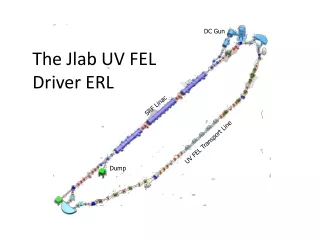
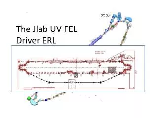
DC Gun. The Jlab UV FEL Driver ERL. IR Wiggler. SRF Linac. Bunching Chicane. UV FEL Transport Line. Dump. Design Requirements. Power recovery from exhaust beam Transverse, longitudinal matching Collective effect/instability control space charge BBU, FEL/RF interaction

DC Gun
E N D
Presentation Transcript
DC Gun The Jlab UV FEL Driver ERL IR Wiggler SRF Linac Bunching Chicane UV FEL Transport Line Dump
Design Requirements • Power recovery from exhaust beam • Transverse, longitudinal matching • Collective effect/instability control • space charge • BBU, • FEL/RF interaction • Loss (halo) management • Delivery of appropriately configured beam to FEL • Transverse, longitudinal phase space management • beam size/divergence: optical mode overlap • Bunch compression: high peak current at FEL • Preservation of beam quality • space charge, wake/collective effects, CSR
Relevant Phenomena • Space charge (transverse, longitudinal) • Inject long (2.5 psec/1.33o rms), low momentum spread (~¼%) bunch (LSC) • BBU • CSR • Compress high charge bunch => potentially degrade beam quality (and get clear signature of short bunch) & put power where you don’t want it… • Other wake, impedance effects • RF heating, resistive wall
Design Concept: add-on to IR Upgrade DC Gun • retain beam dynamics solution from IR • Use same modular approach (and same optics modules) as in IR side of machine • divert beam to UV FEL with minimal operational modification IR Wiggler SRF Linac Bunching Chicane UV FEL Transport Line Dump
gun Design Solution injector Reinjection/recovery transverse match merger Energy recovery through linac Transverse match: linac to arc recovery Bates bend linac Betatron match to wiggler Bates bend Return bypass transport to energy recovery arc wiggler Extraction line to dump Betatron match from wiggler to recovery transport UV bypass transport grafted onto Bates bend
Phase Space Management • Transport system is “functionally modular”: design embeds specific functions (e.g. beam formation, acceleration, transverse matching, bending, dispersion suppression, etc) within localized regions • largely avoids need for S2E analysis • allows use of potentially ill-defined/poorly controlled components • demands design providing operational flexibility • requires use of beam-based methods • needs extensive suite of diagnostics & controls Its a cost-performance optimization (i.e. religious) issue: pay up front for a sufficient understanding of physics, component/hardware quality, or provide operational flexibility and adequate diagnostic capability?
“Modules” for Phase Space Control • Transverse matching – quad telescopes in nondispersed regions; decoupled from longitudinal match • Injector to linac • Linac to recirculator • Match to wiggler • Match out of wiggler to recovery transport • Reinjection match • Longitudinal matching – handled in Bates bends • Path length variable over ~±lRF/2 (for control of 2nd pass RF phase) • Independent control of momentum compaction through third order (M56, T566, W5666) and dispersion through 2nd order (T166, T266) • Relatively decoupled from transverse match • Phase space exchange (IR side only) • H/V exchange using 5 quad rotator for BBU control • Decoupled from transverse, longitudinal matching
Transverse Matching (Linear) • Multiple quad telescopes along transport system massage H/V phase space to match to lattice acceptance • Injector to linac (4 quads) • Linac to recirculator (6 quads) • Match to wiggler (6 quads) • Match wiggler to recovery transport (6 quads) • Reinjection match (6 quads) • Key points • ERLs do not have closed orbits nor do they need to be betatron stable • ERLs may not have uniquely defined “matched” Twiss envelopes • Deliberate “mismatch” (to locally stable transport) may be beneficial • e.g. to manage chromatic aberrations, halo, avoid aperture constraints • Design optimization must explore parameter space to determine “best” choice • Beam envelopes and lattice Twiss parameters are **not** in general the same!
Operationally… • Measure beam envelopes • multislit, quad scan, and/or multi-monitor emittance measurement • Back-propagate results to reference point upstream of matching region • Adjust quads to “match” envelopes to design values and/or acceptance of specific sections of transport system lattice • Caveat: RF focusing is VERY important • dominates behavior in injector • is the “observable” used to set phase on a daily basis • defines injector-to-linac match • Limits tolerable gradient in first (last) cavity
Longitudinal Matching • Space charge forces injection of a long bunch (SRF gradients are too low to preserve beam quality if bunch is short) • Must compress bunch length during/after acceleration to produce high peak current needed by FEL • After lasing, beam energy spread is too large (15-20 MeV) to recover without unacceptable loss • Must energy compress (during energy recovery) to “fit” beam into dump line acceptance The manipulations needed to meet these requirements constitute the longitudinal match
E E E E f f f f E E f f Longitudinal Matching Scenario Requirements on phase space: • high peak current (short bunch) at FEL • bunch length compression at wiggler using quads and sextupoles to adjust compactions • “small” energy spread at dump • energy compress while energy recovering • “short” RF wavelength/long bunch, large exhaust dp/p (~10%) • get slope, curvature, and torsion right (quads, sextupoles, octupoles)
JLab IR Demo Dump core of beam off center, even though BLMs showed edges were centered (high energy tail)
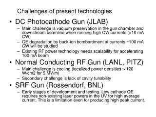
Module Design: Injector • 42 psec (FWHM) 75 (1497/20) MHz green drive laser pulse train with flexibly gated time structure • It’s always the drive laser • DC photocathode (GaAs) gun at 325 kV • Room-temp buncher providing initial longitudinal control • Pair of 5-cell SRF (CEBAF) cavities at 1497 MHz accelerate to ~10 MeV • Quad telescope to match to linac
Cathode • CesiatedGaAs • Excellent performance for R&D system • When charge lifetime limited, get 500 C between cesiations (50k sec, ~14 hrs at 10 mA, many days at modest current), O(10 kC) on wafer • Typically replace because we destroy wafer in an arc event, can’t get QE • When (arc, emitter, vacuum,…) limited, ~few hours running • Not entirely adequate for prolonged user operations • Other cathodes? • Need proof of principle for required combination of beam quality, lifetime? • New results from Cornell!
Wafer 25 mm dia 500 kV/5 MV 350 kV/5 MV Active area 16 mm dia 500 kV/2.5 MV 350 kV/2.5 MV Drive laser 8 mm dia Injector Design and Operation (V) (V w/ PM, MSE) (V w/ PM, BPM) (BPM) • At highest level… • System is moderately bright & operates at moderate power • Halo & tails are significant issue • Must produce very specific beam properties to match downstream acceptance; have very limited number of free parameters to do so • Issues: • Space charge & steering in front end • Deceleration by first cavity • Severe RF focusing (with coupling) • FPC/alignment steering – phasing a challenge • Miniphase • Halo/tails • Divots in cathode; scattered drive laser light; cathode relaxation; … Courtesy P. Evtushenko
Injector Operational Challenges (V) (V w/ PM, MSE) (V w/ PM, BPM) (BPM) • Space charge: have to get adequate transmission through buncher • steering complicated by running drive laser off cathode axis (avoid ion back-bombardment) • solenoid must be reoptimized for each drive laser pulse length • vacuum levels used as diagnostic • precludes use of 1st solenoid for emittance compensation • Must set to provide transmission through buncher, not balance space charge
500 kV/2.5 MV 350 kV/2.5 MV 500 kV/1.5 MV 350 kV/1.5 MV Injector Operational Challenges (V) (V w/ PM, MSE) (V w/ PM, BPM) (BPM) • 1st cavity • decelerates beam to ~175 keV, aggravates space charge; • E(f) nearly constant for ±20o around crest (phase slip) • Normal & skew quad RF modes in couplers violate axial symmetry & add coupling • Dipole RF mode in FPC • Steer beam in “spectrometer”, make phasing difficult • Drive head-tail emittance dilution
Behavior Can Be Counterintuitive… • Example: Proper phasing of JLab injector produces excellent beam quality, stable operation, “completely incorrect” phasing also produces a beam... • one expects that by reversing the source phase (~180o out of phase with the SRF cavities), the beam would be accelerated to a halt • in fact, the beam is captured and accelerated, albeit at poor quality • phase slip retards low energy beam by additional half-RF-period, leads to capture Units: energy: MeV, position: lRF; time: tRF
Injector Operational Challenges (V) (V w/ PM, MSE) (V w/ PM, BPM) (BPM) • FPC/cavity misalignment steering ~ as big as dispersive changes in position • Phasing takes considerable care and some time • Have to back out steering using orbit measurement in linac • RF focusing very severe – can make beam large/strongly divergent/convergent at end of cryounit – constrains ranges of tolerable operating phases • Phasing • 4 knobs available: drive laser phase, buncher phase, 2 SRF cavity phases • Constrained by tolerable gradiants, limited number of observables (1 position at dispersed location), downstream acceptance • Typically spectrometer phase with care every few weeks; “miniphase” every few hours
“Miniphase” (V) (V w/ PM, MSE) (V w/ PM, BPM) (BPM) • System is under-constrained, difficult to spectrometer phase with adequate resolution • Phases drift out of tolerance over few hours • Recover setup by • Set drive laser phase to put buncher at “zero crossing” (therein lies numerous tales, … or sometimes tails...) • Set drive laser/buncher gang phase to phase of 1st SRF cavity by duplicating focusing (beam profile at 1st view downstream of cryounit) • Set phase of 2nd SRF cavity by recovering energy at spectrometer BPM this avoids necessity of fighting with 1st SRF cavity…
Module Design: Merger • Injection line: 3 dipole “Penner bend” • Achromatic (M16, M26 = 0) • Modest M56<0 providing some bunch length control • Very strongly focusing in bend plane; drift-like in non-bend plane • Focusing => space charge management • drift => transverse asymmetry => bad for space charge • Adequate performance at ~100 pC x several mm-mrad level • hard to match across • somewhat archaic design • Reinjection line: achromatic chicane with geometry matched to final dipole of Penner bend • mechanically convenient (fair amount of space)
Numbers r=0.6 m q= 20o normal entry/exit bend plane focal length ~ r/sin q ~ 1.75 m bend-to-bend drift ~ 1.5 m dispersion in center dipole ~0.5 m M56 ~ -0.18 m
Merger Issues (V) (V w/ PM, MSE) (V w/ PM, BPM) (BPM) Low charge (135 pC), low current (10 mA); beam quality preservation notionally not a problem; however… • Can have dramatic variation in transverse beam properties after cryounit • 4 quad telescope has extremely limited dynamic range • Must match into “long” linac with limited acceptance • Matched envelopes ~10 m, upright ellipse • Have to get fairly close (halo, scraping, BBU,…) • Beam quality is match sensitive (space charge) Have to iterate injector setup & match to linac until adequate performance achieved
Module Design: Linac • Three JLab-standard (more or less) cryomodules • Outboard pair: 8 five-cell 1497 MHz cavities • Middle module: 8 seven-cell 1497 MHz cavities • Triplet focusing in warm regions • Relies on RF focusing in front (back) end on 1st (2nd) pass • Wear and tear limits full energy to ~135 MeV or so ~30 m
Module Design: Transverse Match to Recirculator • 6 quad telescope • Match bx,y, ax,y, yx,y from linac to Bates bend • Full transverse envelope match + phase advance allows • management of chromatic aberrations • Choice of phase advance = aberrations destructively interfere • control of turn-to-turn phase advance • BBU suppression 9 MeV beam to dump
Module Design: Bates Bend Requirements • “delivery of appropriately configured beam to wiggler” => • betatron matched to wiggler acceptance • Compressed bunch length • Nondispersed after recirculation transport • “power recovery from exhaust beam” (without loss…) => • Betatron matched to linac acceptance • Decompressed bunch length with S56 & phasing set to insure energy compression during energy recovery • Nondispersed at reinjection => Need (nonlinearly) achromatic recirculation arc with large acceptance, good betatron behavior, and variable path length/momentum compaction (through nonlinear order)
Bates Bend • Originally used as the basis of an energy doubling recirculator (and a demonstration of current doubling and energy recovery in the early ’80s), the MIT implementation had >8.5% momentum acceptance • JLab FEL drivers (IR Demo, IR upgrade) have both used Bates bends
Bates Recirculator • We used the Sargent/Flanz design from MIT because it is really robust, really easy to operate (if you instrument it) and really simple (if you think about it the right way). • Good acceptance (10+%, over 30o RF phase, good focusing properties (esp. if matching in/out uses chromatically balanced telescopes) Ancillary benefit: No simultaneously small b, h, l, so CSR, space charge not aggravated (parasitic crossings not an issue)
Module Design: Bypass to UV FEL • Building design – including location for UV wiggler, predates machine design by over 5 years • IR system funded/built before the UV (for which the building was originally designed) • Bates bend directs beam to IR FEL • UV FEL “must” live in wiggler pit • Wiggler stand height >> beam elevation • Need bypass solution • must provide appropriate matching • Transverse spot size, bunch compression, dispersion suppression • Constrained by pit location
Bypass Concept • Add 1 betatron wavelength in bend plane to image/suppress dispersion • Select out-of-bend-plane phase advance to manage envelopes, aberrations (1/2 betatron wavelength works well) • Use 7 quad FODO transport • Sextupoles at high-dispersion points (at horizontally focusing quads) provide correction of 2nd-order dispersion • Use FODO quad transport between bends to manage dispersion, control betatron envelopes • Reduce bend angle in final dipole of Bates bend to direct beam toward UV wiggler pit • “short out” half of coil pack to reduce bend angle by half • Complete bend when at proper transverse offset
Module Design: Match to Wiggler • Similar to linac-to-arc match • 6 quad telescope (two triplets) • Set transverse envelopes, phase advances
Module Design: Match from Wiggler • Just like previous match: 6 quad telescope, set envelopes, phase advances…
Module Design: Return transport to recovery arc • Reflection of translation from Bates bend to UV backleg
Module Design: Bates Bend • 2nd Bates bend geometrically identical to 1st one • Momentum compactions different (trim quad, sextupole settings) to complete longitudinal match giving energy compression during energy recovery Details to follow…
Module Design: Reinjection Match • More or less a mirror image of linac-to-arc match • Particular care on choice of phase advance needed to ensure “chromatic balance” & adequate momentum aperture • Phase advance between/across telescopes used to control chromatic aberrations • Use “extra” quads in the triplet pairs • Select Twiss parameters in arc with care 9 MeV injected beam
Module Design: Recovery Pass Through Linac • Two issues: • Match (beam loss, halo control, tails, scraping…) • Steering (beam loss, halo control, blah blah blah) • Multipass steering tricky • Best to steer 1st pass “locally” (insofar as possible) and thread 2nd pass through using choice of reinjection orbit • Situation rendered complex by absence of 2-pass BPMs, RF skew quad in 5-cell cavity HOM couplers
Multipass Orbit Correction • Energy of each pass differs at any point of linac • Orbit response to steering differs • Need localized observation & correction • Multipass BPMs - for high-frequency CW bunch trains separated by ½ RF period... • Example: JLab IR Upgrade: orbit bump on 1st pass of linac
Multipass Orbit Correction – Common Transport • “multiple beams” not limited to linac – some ERL geometries use single beamlines for multiple beams • E.g. CEBAF-ER
Module Design: Extraction Line to Recovery Dump • Mirror image of injection merger • Quad triplet after extraction => betatron spot control at dump face • Dispersion ~ 1 m: useful diagnostic for phasing beam during energy recovery & energy compression