Download
1 / 19
190 likes | 392 Views
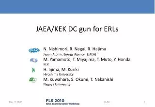
JAEA/KEK DC gun for ERLs. N. Nishimori, R. Nagai, R. Hajima Japan Atomic Energy Agency (JAEA) M. Yamamoto, T. Miyajima, T. Muto, Y. Honda KEK H. Iijima, M. Kuriki Hiroshima University M. Kuwahara, S. Okumi, T. Nakanishi Nagoya Univiersity. Outline.

E N D
JAEA/KEK DC gunfor ERLs N. Nishimori, R. Nagai, R. Hajima Japan Atomic Energy Agency(JAEA) M. Yamamoto, T. Miyajima, T. Muto, Y. Honda KEK H. Iijima, M. Kuriki Hiroshima University M. Kuwahara, S. Okumi, T. Nakanishi Nagoya Univiersity SLAC
Outline • Introduction (Compact ERL, a 500 kV DC gun) • Recent results: High voltage testing of segmented ceramics • HV processing up to 550 kV • 500 kV for eight hours without any discharge • Preparation of electrodes and NEG pumps • Summary SLAC
Compact ERL (test facility) Principal parameters Conceptual design report: KEK Report 2007-7/JAEA-Research 2008-032 SLAC * With some emittance growth due to CSR
Development of a 500 kV photocathode DC gun at JAEA HV terminal low emittance: <=1 mm-mrad (normalized) beam current: >=10 mA segmented insulator • High DC voltage >= 500kV • CockCroft Walton power supply • Segmented insulator with guard rings • High voltage testing • Electrodes and vacuum • Cathode and anode electrodes • Low outgassing material (titanium) • NEG pumps support rod gun chamber cathode anode NEG pumps electron beam SLAC
1200 Field emission from support rod 1000 • Employed a segmented insulator to mitigate field emission problem. • uniform electric field • means to attach rings which guard ceramics against field emission. segmented insulator 800 6.8 MV/m 600 guard rings height (mm) 400 guard rings 8.3 MV/m support rod field emission 200 14.3 MV/m support rod 0 support rod nose beam axis gun chamber -200 ceramic 0 200 400 600 SLAC radius (mm)
500kV DC gun 550kVCockcroft Walton power supply segmented insulator SF6tank 400mm in diam. 730mm 1 m in diam. gun chamber made of titanium 3.8 m SLAC
High voltage testing with a support rod Applied 550 kV to the insulator without a support rod in July 2009. N. Nishimori et al., Proc. of FEL2009, tupc17. support rod Can we apply 500kV to the insulator with a support rod ? 1143.5 mm 101.6 f dummy cup instead of cathode electrode SLAC
HV processing 550kV 4kV/hour • Vacuum pump: 1000L/s-TMP • 190℃ baking for 8 hours • start processing at 3x10⁻⁸[Pa] • one hundred hours to reach 550 kV • quarter hour for each 1kV step from 250 kV to 500 kV • slower processing above 500 kV • Note: The waiting time for vacuum recovery is not included in the integrated time. SLAC R. Nagai et al., “High-voltage testing of a 500-kV dc photocathode electron gun”, to be published in RSI.
HV application after processing outer guard rings and registers RDIV=5.75[GΩ] C.W. + insulator RCW=6.27[GΩ] C.W. only voltage divider: 500MW/segment x 10=5GW Radiation level is within the background. No clear evidence for dark current ROUT=0.1[GΩ] Rout RCW RDIV C.W. SLAC R. Nagai et al., to be published in RSI.
Thank you Pavel Evtushenko at JLab! Dark current estimation without support rod corona discharge with support rod SLAC
HV processing technique C.V. (constant voltage) C.C. (constant current) C.V. C.V. C.C. 0.3s 163mA 164mA discharge charging up 1mA 3GW 0.6nF 1mA C.W. • output register of 100 MW to limit abrupt current drawn from HV in case of discharge • set current limit at V/R+1mA , which helps to stop discharge when average discharge current > 1mA. • Interlock system at vacuum >5x10⁻⁶[Pa] and radiation > 3μSv/h SLAC
Stable operation at 500 kV for 8 hours C.W.:510kV Rdiv:5GΩ Rout:0.1GΩ →500kV@insulator No indication of discharge, local heating due to dark current R. Nagai et al., to be published in RSI. SLAC
Insulator silver brazing silver brazing SUS flange Kovar (Fe-Ni-Co) ring plated with Ni SUS ring Ceramic SLAC TIG welding
Cathode electrode and NEG pumps R251(gun chamber) R198(NEG) R107(NEG) electron beam Φ197(flange) SLAC
Cathode electrode: POISSON calculation 6.75 MV/m cathode R=67 100mm anode forward 10.32 MV/m backward NEG 10.51MV/m 64.5mm NEG SLAC
Cathode electrode f164 head (Ti alloy) body (pure Ti) tail (Ti alloy) 1201 spacer (pure Ti) support rod (pure Ti) SLAC
Vacuum:pump shield against HV cathode cathode 2000L/s NEG 400L/s NEG SLAC
RGA spectrum at preparation chamber 2.35x10⁻⁹ Pa (RGA on) 5x10⁻¹⁰ Pa (off) H2 CANON/ANNELVA: M-201 QA-TDM SEM 1200V 3s/amu H2O CH4 NH3 CO N2 CO2 Hydrogen: 99.3 % of total pressure CP Ti chamber has low outgassing of heavy molecules. SLAC
Summary • 500kV gun status • HV test: 550kV conditioning, 500kV for 8 hours without any discharge • cathode electrode: maximum field <10.5 MV/m, 6.7 MV/m on cathode • NEG pumps: to be installed in gun chamber • vacuum: 1x10⁻⁹ [Pa] (H2 corrected), 99.3 % H2 in preparation chamber • to do list • HV test with electrodes and NEG pumps • improvement of photocathode preparation system • connection between gun and preparation chambers • beam generation SLAC