Download
1 / 27
270 likes | 386 Views
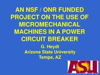
THE USE OF MICROMECHANICAL SWITCHES IN A POWER CIRCUIT BREAK ER. Esma Gel, Gerald T Heydt, Norma Faris Hubele, George G Karady Arizona State University, Tempe, AZ, USA. PSERC. MOTIVATION No major change in CB design in many years Large moving components and size

E N D
THE USE OF MICROMECHANICAL SWITCHES IN A POWER CIRCUIT BREAKER Esma Gel, Gerald T Heydt, Norma Faris Hubele, George G Karady Arizona State University, Tempe, AZ, USA PSERC
MOTIVATION • No major change in CB design in many years • Large moving components and size • Need for vacuum or SF 6 enclosure • No synchronous switching Application of electronics components and MEMS switches allow miniaturization and zero current switching
Micro-switch based Circuit Breaker Concept
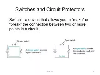
Conceptual circuit diagram for an ac circuit breaker • Circuit breaker contains two switches • Positive switch operates in the positive cycle • Negative switch operates in the negative cycle
Switching string assembly with several strings connected in parallel. (Positive switch only) Voltage rating is increased by switching additional units in series Current rating is increased by switching additional units in series
Equivalent circuit of a switching string Closed switches equivalent is the contact resistance Open switches equivalent is the diode voltage
Equivalent circuit modeling the non- simultaneous operation of the switches.
Current distributions when all string except one is turned on with one millisecond delay. A. Inductive load current B. The closing of all switches in string 1 eliminated the diodes and inserted the contact resistances C. Simultaneously the current of the other two strings reduced to zero, because the diodes become reverse biased. Simulation of switch closing
Current distribution during current interruption. A). String current when one string is turned off with 1 msec delay. B) String current when all strings except one is turned off with 1 msec delay. The short circuit current is interrupted with a half cycle Simulation of switch opening
Current injection circuit for interruption of DC current. • DC current interruption requires current injection: • Charge capacitor produces current oscillation. • During the negative cycle the switches are opened • At zero crossing the diodes interrupts the current
The coil under the switch is energized The generated magnetic field moves the permanent magnet towards the base This closes the contact The problem is that the insulation has to withstand 7.2 kV between the contact and the magnet. No switch is available to meet with this requirement
ASU started to develop MEMS switches for this circuit breaker A matrix contains 4 x 4 = 16 switches is being studied Several sample has been built and tested This matrix permits the formation of 4 switching strings with 4 MEMS connected in series 1328 μm 1175 m 4 x 4 Matrix of switches using aluminum metalization
Control solenoid Reduced scale circuit breaker Switching string
The technical data of the developed small scale circuit breakerRated current: 8 A steady stateInterruption current: 50 A for a half cycleRated voltage: 4000 VBIL: 95 kVNumber of switches in series in a single string: 10Number of strings in parallel: 8
RELIABILITY ANALYSIS • States of an individual switching unit • Most probable failure mode is in closed condition
Conclusions • The study proved that the micro-switched based medium voltage circuit breaker is feasible. • It offers small size, zero current switching and interruption of short circuit current within a half cycle.
The specific results are: • Development of novel concept for CB’s using switching matrix and switching string. • Development of a method to analyze the effect of none simultaneous operation of switches in a switching string assembly. • Reliability analysis of switching matrix. • Building of a proof of principles switching string assembly to experimentally proof the validity of the concept. • Proposal for development of a new type of MEMS device and the specification of the new device. • Development of a novel analytical model for the reliability analysis of the switching matrix.
FUTURE WORK • Finalization the analytical technique for operation of large switching matrixes, • Improvement of reliability analysis and • Testing the proof of principle switching assembly. • Detailed design of the MEMS based switch • Implementation of the educational objective PROBLEM • Lack of suitable MEMS device in the market
Acknowledgement • The authors would like to acknowledge the support of NSF and the Navy. • The authors thank to Prof B. Kim of ASU and • Graduate students: Mr. Neil Shah, Daniel S. James II and Rahim Kasim for their contribution.