Download
1 / 26
320 likes | 905 Views
CHAPTER 4 Combinational Logic Design – Multiplexers (Sections 4.5). Multiplexer. “ Selects ” binary information from one of many input lines and directs it to a single output line. Also know as the “ selector ” circuit,

E N D
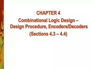
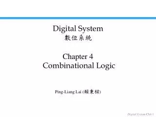
CHAPTER 4 Combinational Logic Design – Multiplexers (Sections 4.5)
Multiplexer • “Selects” binary information from one of many input lines and directs it to a single output line. • Also know as the “selector” circuit, • Selection is controlled by a particular set of inputs lines whose output depends on the combination of the data input lines. • For a 2n-to-1 multiplexer, there are 2n data input lines and n selection lines whose bit combination determines which input is selected.
A B Y 0 0 D0 0 1 D1 1 0 D2 1 1 D3 4-to-1 MUX B A Y=A’B’D0+A’BD1+AB’D2+ABD3 =∑miDi 2n-1 i=0
8-to-1 MUX 74LS155 Y w
8-to-1 MUX Y= C’B’A’D0+ C’B’AD1+ C’BA’D2+C’BAD3+ CB’A’D4+ CB’AD5+ CBA’D6+ CBAD7 =∑miDi i=2n-1 i=0
Multiplexer Expansions • Until now, we have examined single-bit data selected by a MUX. What if we want to select m-bit data/words? Combine MUX blocks in parallel with common select and enable signals • Example: Construct a logic circuit that selects between 2 sets of 4-bit inputs (see next slide for solution).
Example: Quad 2-to-1 MUX • Uses four 2-to-1 MUXs with common select (S) and enable (E). • Select line chooses between Ai’s and Bi’s. The selected four-wire digital signal is sent to the Yi’s • Enable line turns MUX on and off (E=1 is on).
Example: Quad 4-to-1 MUX 74LS153(P43)
Multiplexer Expansions A32-to-1multiplexer using two 74xx150ICs(P144)
Multiplexer Expansions A 32-to-1 multiplexer using four 8-to-1 multiplexers and a 2-to-4 decoder(P145)
Implementing Boolean functions with Multiplexers • E.g. Using an 8-to-1 multiplexer to realize the Boolean function F=f(x,y,z)=∑(1,2,4,5,7) Y= C’B’A’D0+ C’B’AD1+ C’BA’D2+C’BAD3+ CB’A’D4+ CB’AD5+ CBA’D6+ CBAD7 =∑miDi i=2n-1 i=0 F=f(x,y,z)=∑(1,2,4,5,7) =x’y’z+x’yz’+xy’z’+xy’z+xyz C=x,B=y,A=z D0=D3=D6=0 D1= D2= D4= D5= D7=1
Implementing Boolean functions with Multiplexers C=x,B=y,A=z D0=D3=D6=0 D1= D2= D4= D5= D7=1
D0 D1 4-1 MUX D2 F Z Z’ 1 Z D3 B A Using an 4-to-1 multiplexer to realize the Boolean function F=f(x,y,z)=∑(1,2,4,5,7) F=f(x,y,z)=∑(1,2,4,5,7)=x’y’z+x’yz’+xy’z’+xy’z+xyz XY 10 Z 11 00 01 Y Y’ Y 1 X X’ 1 X 1 1 0 1 1 1 1 D0=Z D1=Z’ D2=1 D3=Z D0=Y D1=Y’ D2=Y’ D3=1 D0=X D1=X’ D2=1 D3=X X Z Z Y Y X F=X’Y’D0+X’YD1+XY’D2+XYD3
Implementing Boolean functions with Multiplexers • Exe. implement function using a 4-to-1 MUX F(X,Y,Z) = Σm(1,2,6,7) F(A,B,C) = m(1,3,5,6).
Implementing Boolean functions with Multiplexers • F(X,Y,Z) = X’Y’Z + X’YZ’ + XYZ’ + XYZ = Σm(1,2,6,7) • There are n=3 inputs, thus we need a 22-to-1 MUX • The first n-1 (=2) inputs serve as the selection lines
D0 D1 4-1 MUX F D2 D3 B A B A Implementing Boolean functions with Multiplexers F(A,B,C) = m(1,3,5,6). AB 10 C 11 00 01 0 1 1 1 1 1 When A=B=0, F=D0=C When A=0, B=1, F=D1=C When A=1, B=0, F=D2=C When A=B=1, F=D3=C’
Implementing Boolean functions with Multiplexers A B C F 0 0 0 0 When A=B=0, F=C 0 0 1 1 0 1 0 0 When A=0, B=1, F=C 0 1 1 1 1 0 0 0 When A=1, B=0, F=C 1 0 1 1 1 1 0 1 When A=B=1, F=C’ 1 1 1 0
MUX implementation of F(A,B,C) = m(1,3,5,6) A B C C F C C’
Implementing Boolean functions with Multiplexers E.g. Consider the following Boolean expression given in sum-of-product form: F(x1,x2,x3)=x1’x2’+x1x2’+x1x3 Derive a circuit for using only 2-to-1 multiplexers.
X1X2 00 01 11 10 X3 1 1 0 1 1 1 1 Implementing Boolean functions with Multiplexers F(x1,x2,x3)=x1’x2’+x1x2’+x1x3 = x1’x2’ x3 ’+ x1’x2’ x3 + x1x2’ x3 ’+ x1x2’ x3 + x1x2x3 =∑(0,1,4,5,7) D0=X2’ D1=X2’+X3 How to derive it only from function?
X2’ D0 2-1 MUX F ≥1 X3 D1 A X1 Implementing Boolean functions with Multiplexers D0=X2’ D1=X2’+X3
Implementing Boolean functions with Multiplexers Exe. F(A,B,C,D)=∑m(1,2,4,9,10,11,12,14,15) Derive a circuit for using 4-to-1 multiplexers.
MUX as a Universal Gate • We can construct OR, AND, and NOT gates using 2-to-1 MUXs. Thus, 2-to-1 MUX is a universal gate. NOT AND OR 1 x1 z = x1+ x1’x0 = x1x0’ + x1x0 + x1’x0 = x1 + x0 z = 0x + 1x’ = x’ z = x1x0 + 0x0’ = x1x0
Homework • P179: 25.(1), 26.(2)