FPGA Implementation of OFDM Receiver for Architecture Bottlenecks Identification
This project aims to implement an OFDM receiver on an FPGA to enable performance testing and identification of architecture bottlenecks. Utilizing Simulink via Matlab and Xilinx ISE 12.2, the project involves creating block diagrams for demodulation, phase shifting, modulation, demultiplexing, and multiplexing processes. The development of IQ multipliers and TDD/TDM modules is crucial for signal processing. Testing will be conducted using FFT, Sinc function, XUP5 Dram, and XC5VLX110T hardware, with a focus on data input/output and cycle delays.

FPGA Implementation of OFDM Receiver for Architecture Bottlenecks Identification
E N D
Presentation Transcript
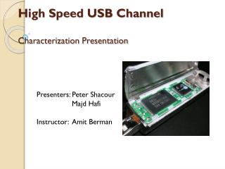
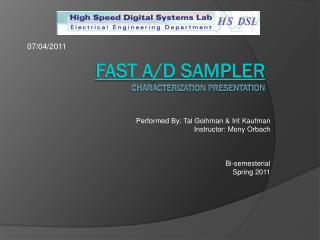
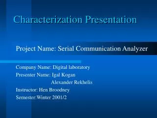
Characterization Presentation OFDM implementation and performance test Performed by: Tomer Ben Oz Ariel Shleifer Guided by: MonyOrbach Duration: Semester
motivation • Tera-Santa project in the Technion needs implementation. • FPGA implementation of OFDM receiver will enable performance test and identification of architecture bottlenecks.
Project goals • Implementation of an OFDM receiver on a FPGA. • Give a good base and tools for future bottlenecks and capability testing.
Working environment • Simulink via Matlab • Xilinx ISE 12.2 • Modelsim
Demodulator Block diagram Phase multiplier – Shifts the phase of the signal back to its original phase. Inputs: Q in, I in – Current sample’s values; A,B – Correction factors • outputs: Q out, I out – The correct signals values.Look Up Table(Qam4) – Translate the signal back to data in bits. • Inputs: Q, I – The correct signals values.outputs: QAM4_OUT – The translated data
Phase Multiplier Block diagram • IQ multiplier– Shifts the phase of the signal back to its original phase. • Inputs: Q in, I in – Current sample’s values; A,B – Correction factors • outputs: Q out, I out – The correct signals values.TDD– Time Domain Demux • Inputs: 8 bits.outputs: D0-3 –each output channels the input data in an upwards order. • TDM– Time Domain mux • Inputs: D0-3 - 8 bits each.outputs: The output channels the input data in an upwards order.
IQ multiplier Block diagram • IQ multiplier– Shifts the phase of the signal back to its original phase. • First degree (multiplication) Delay is 3 cycles • Second degree (adder) Delay is 1 cycle • Hence we chose TDD and TDM to have 4 inputs\outputs
Testing environment XUP5 Dram XC5VLX110T Dram Data In Data out counter counter