Lab 1: GPIO
Lab 1: GPIO. GPIO on MSP430. 6 ports on MS430F1611 Port 1 Port 2 Port 3 Port 4 Port 5 Port 6 Each port has 8 pins Px.0 ~ Px.7. Multiplexed. Port pins are often multiplexed Means it may have more than one function Example: P1.0/TACLK It can be P1.0 GPIO Or it can be TACLK

Lab 1: GPIO
E N D
Presentation Transcript
GPIO on MSP430 • 6 ports on MS430F1611 • Port 1 • Port 2 • Port 3 • Port 4 • Port 5 • Port 6 • Each port has 8 pins • Px.0 ~ Px.7
Multiplexed • Port pins are often multiplexed • Means it may have more than one function • Example: P1.0/TACLK • It can be P1.0 GPIO • Or it can be TACLK • You must select the function you want
Select Direction • Each pin can be configured as input or output • When set to output • You can configure it to be • High: voltage is Vcc (Supply voltage) • Low: voltage is GND (Ground) High: 3.3V Low: 0V
Input • When you select a pin as input direction, a corresponding bit in peripheral register will • Set to 0 when input voltage is low • Set to 1 when input voltage is high High: 3.3V 1 0 Low: 0V
Interrupts • Only P1 and P2 are interruptible • For each pin in P1 and P2, you can enable or disable its interrupt • Enable means it will detects interrupt • Disable means nothing happen when interrupt occur
How to Detect Interrupts • For GPIO, interrupt is detected when a transition occur • Low to high transition: • High to low transition: • You must define which one you want to detect 3.3 V 0 V 3.3 V 0 V
Interrupt Flag • When the MCU detects an interrupt • A corresponding bit in peripheral register will set to 1 • Branch to ISR • You must clear the GPIO interrupt flag in software • Means you must set the bit to 0 • or the program will re-enter the ISR again
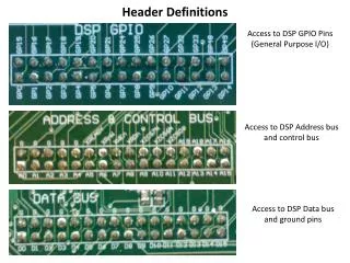
GPIO Registers • Each GPIO port has four registers • Input: PxIN • Output: PxOUT • Direction: PxDIR • Port Select(function select): PxSEL • P1 and P2 have three more • Interrupt flag: PxIFG • Interrupt edge select: PxIES • Interrupt enable: PxIE • Each register is 8-bit long • x represent the port number
How to Select Function • You want to select this pin as GPIO(P1.0) function • The register related to function select • Port Select(function select): PxSEL • This is port 1, so the related register is P1SEL • From user guide
How to Select Function • P1SEL is 8-bit long • Each bit corresponding to a pin in the port 7 0 P1SEL P1.6/TA1 P1.4/SMCLK P1.2/TA1 P1.0/TACLK P1.7/TA2 P1.5/TA0 P1.3/TA2 P1.1/TA0
How to Select Function 7 0 • You want select P1.0/TACLK as P1.0 • Set the corresponding bit to 0 • In C: P1SEL = P1SEL & 0xFE; P1SEL P1.6/TA1 P1.4/SMCLK P1.2/TA1 P1.0/TACLK P1.7/TA2 P1.5/TA0 P1.3/TA2 P1.1/TA0 7 0 P1SEL
Setting Bits Hexadecimal • P1SEL = P1SEL & 0xFE; • P1SEL &= 0xFE; • Usually, we use hexadecimal in setting registers • 0xFE = 11111110 (binary number) • Why P1SEL &= 0xFE; • Why not P1SEL = 0xFE; • The other registers are similar • check user guide
GPIO Interrupt • All P1 pins source a single interrupt vector, and all P2 pins source a different single interrupt vector. • Interrupts generated by P1.0, P1.1, …, P1.7 all go to same ISR • How do you know which one generate the interrupt • check interrupt flag
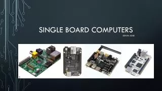
Hardware • LEDs • Switches • Keypad
LEDs • This is a typical connection • When P1.1 set to high • DVcc = VP1.1 • no current flow • When P1.1 set to low • VP1.1 = 0 • Current flow through, turn on the LED • GPIO can use as an On/Off control R DVcc Vanode Vcathode
Control LEDs • Look at Taroko schematic • which pins the LEDs connected to • These pins should be input direction or output direction? • How to set these pins to high (or low)
Will This Work • Maybe, but you shouldn’t do this R Vcathode Vanode
Max Current Source/Sink • Each pin has a maximum amount of current it can provide(source) or accept(sink) • For MSP430 • Max source: 6mA • Max sink: 6mA • Usually it can sink more current than it can source • You cannot use those pin as a power source (or sink) for any sensor/circuit directly
Transistors • One of the fundamental building block of ICs • Two type: NPN, PNP • B: Base • C: Collector • E: Emitter • We will talk about NPN transistor • most commonly used
Functional Model • A base current IB flows only when the voltage VBE across the base-emitter junction is 0.7V or more • Ic = hFE × IB (hFE is current gain) • The collector-emitter resistance RCEis controlled by the base current IB: • IB= 0 RCE = infinity transistor off • IBsmall RCE reduced transistor partly on • IBincreased RCE = 0 transistor full on ('saturated')
Transistor as An On/Off Switch • Application Circuit • Load is turn on when chip output is high • Choose a proper transistor and base resistor RB
How To Choose • Transistor • Two parameter: Ic and hFE • Ic(max) must be larger than Iload (Ic) • Ic = hFE × IB hFE(min) > 5 x ((Ic) /(maximum output current from the chip)) • RB • RB = (Vcc × hFE) / (5 × Ic) • choose the nearest standard value resistor
Switches • Operation • Open: A and B are not connected in normal state • Close: When you press the button, A and B are connected • Typical circuit • When the switch is open, voltage of USERINT stay at high • When the switch is close, voltage of will be low A B
Pull-up Resistor • R4 is a pull-up resistor • keep USERINT at high • What if we don’t have R4 • When it is open, USERINT is still high • When it is close • Short circuit USERINT
Typical Value • Typical value of pull-up resistor • 10K ohm, 47K ohm, 100K ohm • Amount of current flow through when it close • I = V/R; Vcc = 3.3V, R = 10K ohm • I = 0.00033A = 330 μA • 330 μA, does it matter • for some type of switch, it is ok • close time very short • but not all, eg. reed switch
Value of Pull-up • To save power, can we use very large pull-up resistor? • ans: No
Impedance • Resistance: R = V/I • relation ship between the magnitude of the voltage and current • Impedance: Z = V/I (there are complex number) • relation ship between the magnitude and phase of the voltage and current
Input Impedance This is a simplified analysis, we consider impedance as a resistance. Impedance is more complex than a simple resistance Vcc R1 Ri Z Ri
Resistors in series • Ri is the input impedance of MSP430 GPIO pin • TI didn’t specify its value • but it should be larger than 10M ohm • R1 is pull-up resistor • if R1 is too large – R1 = Ri • then VMCUpin = Vcc / 2 • it is no longer a high state Vcc R1 VMCUpin Ri
Debounce Capacitor • C9 is a debounce capacitor • Bounces • It could generate more than one interrupts when the switch is pressed
HW/SW debounce • Hardware debounce • Capacitor will charge when the switch is open, and it will discharge when the switch is close (pressed) • Pros: smooths the line • Cons: increase the response time • Software debounce • Delay some time in the ISR • How long • you have to try out
Keypad • This is a 3x4 matrix keypad • When you press a button, a pin in X and a pin in Y is connected • How to interface to MSP430?
Today’s Labs • Flash a LED on Taroko • Toggle a LED when UserInt switch on Taroko pressed • Control on/off of a LED by UserInt switch, control another by reed switch • (Extra Credit) Connected a 3x4 Keypad to Taroko, flash the LEDs Red Green Yellow Flash once Flash twice
JTAG Driver • C:\Program Files\IAR Systems\Embedded Workbench Evaluation 4.0\430\drivers\TIUSBFET\WinXP